
 简体中文
简体中文
 English
 Français
 日本語
日本語
 Deutsch
0086-574-88881358
0086-574-88473625


News
Jul 24, 2026
A gas pressure regulator takes gas stored or transported at a high, variable pressure and reduces it to a lower, stable pressure that downstream equipment can use safely. It is a pressure control device, not a flow control device — the regulator does not measure or limit how much gas passes through; it only manages the pressure at which that gas is delivered. Every regulator relies on three internal components working together: a loading mechanism (almost always a spring), a sensing element (a diaphragm or piston that reacts to outlet pressure changes), and a control element (a valve seat and plug that opens or closes to compensate). Whenever supply pressure exceeds what a process line, instrument, or appliance is rated for, a regulator becomes mandatory rather than optional. High-pressure cylinders and bulk storage tanks almost always require at least one stage of regulation before the gas reaches a burner tip, analyzer, or reactor vessel. Skipping this step is one of the most common causes of equipment damage and unplanned downtime in industrial gas systems. Regulator selection starts with matching the device category to the application, not just the pressure numbers on a spec sheet. Four broad categories cover almost every industrial use case. Line regulators sit at the point of use on low-pressure distribution piping. They are common wherever a plant already runs a central gas header and individual workstations or burners need a final, tightly held pressure drop. These are built for economy and long service life in noncorrosive environments — general plant air and gas lines, pilot plants, and maintenance shops. They are the default choice when the gas is non-reactive and purity requirements are modest. High-purity regulators use metal diaphragms and specially finished seats and seals to minimize diffusion and outgassing. Semiconductor fabrication, analytical instrumentation, and specialty gas blending all depend on this category to prevent trace contamination. Oxygen, acetylene, fluorine, and other reactive or corrosion-prone gases require regulators built with compatible wetted materials and, in many cases, cleaned and assembled under strict contamination-control procedures. Ultra-high-pressure and corrosion-service regulators also fall into this group. Beyond category, regulators are also classified by staging. Single-stage regulators reduce pressure in one step and are widely favored for their simple, low-maintenance design — industry data for 2026 points to single-stage units holding close to 59 percent of the U.S. industrial gas regulator market by type, largely because of that mechanical simplicity. Two-stage regulators reduce pressure across two separate diaphragm-and-spring assemblies, which keeps outlet pressure far more stable as the supply cylinder empties and its inlet pressure drops. Once gas enters the regulator body, the sequence below repeats continuously to hold outlet pressure steady: This constant balancing act is why regulator sizing matters. A unit that is oversized for the actual flow demand will hunt or oscillate around the set point; one that is undersized will show excessive droop — a drop in outlet pressure as flow demand increases — even though the set point on the gauge looks correct at zero flow. Two regulators with identical outlet pressure ratings can behave very differently under real operating conditions. The specifications below are what separate a reliable installation from a chronic troubleshooting problem. For high-pressure cylinder service, first-stage regulators typically reduce a 200 to 400 bar static cylinder charge down to a working range of roughly 5 to 50 bar, which is then either used directly or fed into a second-stage regulator for final trim. Dual-inlet configurations, which allow two cylinder banks to feed a single regulator body, are common wherever a critical process cannot tolerate an interruption while cylinders are swapped. Regulator specification sheets reference a recurring set of standards bodies, and knowing what each one actually covers helps when comparing quotes from different manufacturers. None of these standards dictate which brand or model to buy — they define minimum construction and testing thresholds. A regulator built to the applicable standard for its pressure class and gas service gives a baseline of safety, but application-specific factors such as flow demand, ambient temperature, and gas purity still need separate evaluation. Choosing the wrong category of regulator is a far more common failure point than choosing the wrong brand. The table below outlines starting points by application type. Inert gases such as argon, helium, and nitrogen dominate regulator demand overall, with 2026 market estimates placing this gas category above 61 percent share of the U.S. industrial gas regulator market — largely because of their non-reactive behavior around flammable or explosive process materials. Oil and gas remains the leading end-use segment by a wide margin, reflecting how much regulation infrastructure sits between wellhead pressures and downstream processing equipment. Most premature regulator failures trace back to installation shortcuts rather than manufacturing defects. The following practices consistently reduce field problems: Diaphragms, seats, and springs are wear items regardless of build quality. A practical baseline schedule includes a visual inspection every three months, a full functional test of set point and lock-up pressure every six to twelve months, and a complete internal rebuild or replacement on a cycle set by the gas service — corrosive or high-cycling applications need shorter intervals than clean, low-flow instrument gas lines. An oft-cited industry estimate holds that roughly 30 percent of industrial systems experience some form of pressure-management-related inefficiency or failure, underscoring why a documented inspection schedule matters as much as the initial regulator specification. Two shifts are reshaping regulator specification this year. First, IoT-enabled smart regulators with integrated pressure and flow monitoring are moving from niche instrumentation projects into mainstream plant specifications, giving operations teams remote visibility into set point drift before it causes a process upset. Second, the expansion of hydrogen infrastructure and clean-energy projects is creating new demand for regulators rated for hydrogen's smaller molecular size and higher embrittlement risk, pushing material selection toward hydrogen-compatible seals and body alloys. Neither trend changes the fundamental mechanics described earlier in this guide — the diaphragm, spring, and seat still do the work. What changes is the layer of monitoring and material science wrapped around that core mechanism as facilities push for tighter process control and broader gas compatibility. A single-stage regulator drops pressure from inlet to outlet in one step, which is simpler and less expensive but allows more outlet pressure drift as the supply cylinder empties. A two-stage regulator splits the reduction across two internal stages, holding outlet pressure far steadier across the full life of the cylinder charge. Only if the wetted materials, seals, and inlet connection are rated for every gas in question. Oxygen, fuel gases, and corrosive gases each carry specific material compatibility requirements, and mixing services on a single regulator not rated for all of them creates a contamination or safety risk. This is lock-up pressure, a normal characteristic of spring-loaded regulator design. A small amount of additional seat travel is needed to fully close the valve, which allows outlet pressure to climb slightly above the set point. Regulators with tighter lock-up specifications are available for processes sensitive to this rise. Flow capacity is expressed as a Cv value, representing the flow rate a regulator can pass at a given pressure drop without excessive droop. Sizing a regulator requires matching this Cv rating against the actual peak flow demand of the downstream process, not just the pipe size. Rapid pressure drop across the orifice causes gas expansion cooling, known as the Joule-Thomson effect. At high flow rates with a large pressure differential, this cooling can drop the regulator body temperature below freezing, especially in humid ambient conditions, leading to visible ice formation. A general baseline is a visual check every three months and a full functional test of set point and lock-up performance every six to twelve months, with more frequent intervals for corrosive gas service or high-cycling applications. No. A regulator maintains a set delivery pressure; flow rate is determined separately by downstream demand, orifice sizing, and any dedicated flow control devices installed in the line.What a Gas Pressure Regulator Actually Does
The Main Categories of Gas Pressure Regulators
Line Regulators
General-Purpose Regulators
High-Purity Regulators
Special Service Regulators
How the Internal Mechanism Responds to Pressure Changes
Specifications That Actually Determine Performance
Specification
What It Tells You
Maximum inlet pressure
Highest supply pressure the body and seat can safely accept
Outlet pressure range
Adjustable delivery pressure band the spring assembly can hold
Flow capacity (Cv)
Maximum flow the orifice and trim can pass without excessive droop
Droop
Outlet pressure loss as flow rate increases from zero to rated capacity
Lock-up pressure
Pressure rise above set point once downstream flow demand reaches zero
Supply pressure effect
How much outlet pressure shifts as inlet pressure falls during cylinder depletion
Standards That Govern Regulator Design and Testing
Matching a Regulator to the Application
Application
Recommended Category
Welding and cutting (argon, CO2 blends)
General-purpose, single-stage
Analytical instrumentation and calibration gas
High-purity, two-stage
Oxygen and acetylene service
Special service, gas-specific fittings
Continuous process feed from bulk cylinder banks
Two-stage with dual-inlet manifold
Point-of-use plant distribution lines
Line regulator
Installation Practices That Prevent Early Failures
Maintenance Intervals and Early Warning Signs
Routine Maintenance Checkpoints
Signs a Regulator Needs Attention
Where Regulator Technology Is Heading in 2026
Frequently Asked Questions
What is the difference between a single-stage and two-stage gas pressure regulator?
Can one regulator be used for multiple gas types?
Why does outlet pressure rise when downstream flow stops?
How is regulator flow capacity determined?
What causes a regulator to freeze or ice over during operation?
How often should a gas pressure regulator be inspected?
Does a gas pressure regulator control flow rate?
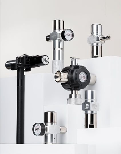
Jul 24, 2026
A pressure regulator is a mechanical device that automatically reduces a high, often fluctuating, inlet pressure down to a stable, lower outlet pressure that a downstream system can safely use. Instead of leaving equipment exposed to whatever pressure a cylinder, compressor, or pipeline happens to be delivering at a given moment, the regulator holds the working pressure inside a narrow, predictable band even as upstream conditions change. The short answer: a pressure regulator uses a spring-loaded diaphragm and a valve seat to balance incoming force against a preset spring tension, opening or closing the flow path automatically so that the outlet pressure stays close to the set point regardless of how much the supply pressure or downstream demand shifts. Inside the body, three parts do almost all of the work. The diaphragm senses outlet pressure and moves in response to any change. The spring pushes back against that movement with a force set by an adjustment screw or knob, which is how the target pressure is dialed in. The valve seat and poppet physically open or close the orifice based on the balance between the diaphragm and the spring. When downstream pressure drops below the set point, the spring pushes the diaphragm down, the poppet lifts, and more flow is admitted. When downstream pressure rises above the set point, the diaphragm pushes back against the spring and the poppet closes toward the seat, throttling flow until balance is restored again. Every pressure regulator, whether it controls gas, air, water, or steam, cycles through the same basic sequence of events every time demand or supply changes. Understanding this cycle makes it much easier to diagnose problems later and to compare regulator designs on a like-for-like basis. This constant self-correction is what separates a regulator from a simple fixed orifice or manual valve. A manual valve holds a fixed opening regardless of what happens downstream; a regulator actively adjusts that opening in real time to hold pressure steady. Regulator designs are grouped by how many pressure-reduction stages they use and by how the sensing and actuation mechanism is built. Choosing the wrong category is one of the most common causes of unstable downstream pressure, so it is worth comparing the main families side by side before specifying a part. Industry data on industrial gas regulators consistently shows single-stage designs holding the largest overall share of installed units, largely because they are simpler to install and maintain across general-purpose plant air and inert gas lines. Dual-stage and pilot-operated designs make up most of the remaining share, concentrated in applications where inlet pressure varies widely or where flow demand is large enough that a single spring cannot hold tight tolerance on its own. A regulator that looks correct on paper can still fail in service if one of the following specifications is mismatched to the real operating conditions. Reviewing all six together, rather than any single number in isolation, is what actually prevents an undersized or oversized selection. Correct sizing comes down to six governing factors working together: inlet pressure, outlet pressure, flow rate, temperature, the media being handled, and the line size the regulator connects into. Skipping any one of these and sizing on a single number, such as pipe diameter alone, is the most frequent cause of oversized or undersized regulators reaching the field. A regulator's published Cv is normally measured at fully open, choked-flow conditions. Sizing a regulator to run near that maximum Cv during normal operation is a mistake, because a regulator operating wide open is no longer actively regulating anything. A better target is a regulator whose required operating Cv sits well below the rated maximum, leaving headroom for the poppet to modulate. The practical sizing sequence most engineers follow looks like this: Where inlet pressure is expected to swing widely, for example a cylinder discharging from a high fill pressure down toward a low minimum, a dual-stage or pilot-operated design will typically hold outlet pressure far more consistently than a single-stage unit sized for the same nominal flow. Pressure regulators appear anywhere a process needs a stable working pressure that differs from the supply pressure available. The specific duty changes considerably from one sector to the next. The wetted material of a regulator body, seat, and diaphragm decides whether it will hold up in service or degrade quickly. Two body materials cover the large majority of industrial applications, with a smaller set of diaphragm materials layered on top depending on the media. As a practical rule, corrosive, toxic, or oxidizing gases justify the added cost of stainless steel and fluoropolymer internals, while clean, inert, and general plant air rarely need anything beyond a well-made brass regulator with nitrile seals. Pressure regulators are largely maintenance-free by design, but the internal diaphragm, spring, and seat do wear over time, particularly in high-cycle or dirty gas service. Catching the following warning signs early prevents an unplanned shutdown. Routine inspection of the inlet filter, periodic exercise of the adjustment mechanism, and keeping a spare diaphragm kit on hand for critical services are the three most cost-effective maintenance habits available for this class of equipment. Several shifts are changing how buyers specify regulators this year. Automation and remote monitoring are moving from a premium feature to an expected option, particularly for facilities managing multiple gas panels across a plant. IoT-enabled regulators that report pressure, cycle count, and diaphragm condition back to a central system are increasingly specified for critical services where an unplanned pressure excursion would be costly. Growth in hydrogen and other clean-energy gas infrastructure is also pushing demand for regulators rated for the specific compatibility and cycling requirements that hydrogen service imposes, since hydrogen behaves differently from inert gases in terms of material permeation and embrittlement risk. At the same time, inert gases such as argon, helium, and nitrogen remain the largest single gas category served by industrial regulators, reflecting how widespread shielding, purging, and blanketing duties are across manufacturing. Buyers evaluating a regulator purchase in 2026 increasingly weigh total lifecycle monitoring capability alongside the traditional criteria of pressure range, Cv, and material compatibility, rather than treating remote monitoring as an optional add-on. A single-stage regulator reduces inlet pressure to outlet pressure in one step using one spring and seat, which works well when supply pressure is fairly stable. A dual-stage regulator splits that reduction across two internal stages, which keeps outlet pressure far steadier as the supply pressure falls, such as when a cylinder empties from full to near-empty. Start from the actual minimum and maximum flow rate the process requires, along with the allowable pressure drop across the regulator, then compare that calculated value against the manufacturer's flow curve rather than the single maximum Cv listed in a catalog. The regulator should be sized so normal operation sits comfortably below its rated maximum flow, not at it. Only if the wetted materials, seals, and thread or fitting connections are all confirmed compatible with each gas in question. Swapping a regulator between an inert gas and a corrosive or oxidizing gas without checking material compatibility risks seal degradation, contamination, or in some cases an unsafe reaction. This effect, known as droop, happens because the diaphragm needs a small amount of unbalanced force to keep the valve open further as flow increases, which slightly lowers the sensed outlet pressure. Pilot-operated designs generally show less droop than direct-operated designs because the pilot stage amplifies the correcting force. There is no single fixed interval, since wear depends heavily on cycle frequency, gas cleanliness, and operating pressure. High-cycle or critical services benefit from a scheduled inspection of the diaphragm and seat, while low-cycle general plant air regulators can often run for years with only periodic visual checks for leaks or pressure creep. A steady leak from the bonnet vent almost always indicates that the diaphragm has developed a tear or pinhole, allowing process gas to migrate past it and escape through the vent that is designed to relieve any such leakage safely. Replacing the diaphragm typically resolves this without needing to replace the entire regulator.What Is a Pressure Regulator and How Does It Work
Core Components and the Regulation Cycle
Main Types of Pressure Regulators Compared
Type
How It Reduces Pressure
Best Suited For
Single-stage regulator
One spring and seat reduce inlet pressure to outlet pressure in a single step
Simple systems with a fairly stable inlet pressure and moderate flow needs
Dual-stage (two-stage) regulator
Two separate reduction steps inside one body, smoothing out large inlet swings
Cylinder supply that drops steadily as the cylinder empties, where steady outlet pressure matters
Direct-operated (spring-loaded) regulator
Spring acts directly on the diaphragm and poppet with no pilot assistance
Low to moderate flow, simple and low-flow applications where compact size matters
Pilot-operated regulator
A smaller pilot regulator controls a larger main valve, multiplying accuracy and capacity
High-flow or high-pressure systems such as transfer stations and large industrial lines
Back-pressure regulator
Holds a set pressure upstream of itself rather than downstream
Protecting sensitive equipment upstream, venting, and relief-style duties
High-purity regulator
Metal diaphragms and high-purity seats minimize internal contamination and trapped volume
Semiconductor, laboratory, and analytical gas lines where trace contamination is unacceptable
Key Specifications to Check Before Buying a Pressure Regulator
Specification
Why It Matters
Maximum inlet pressure
Sets the pressure rating the body and seat must safely withstand, including transient spikes
Outlet pressure range
Confirms the regulator can be adjusted precisely within the band the process actually needs
Flow coefficient (Cv)
Indicates how much flow the regulator can pass at a given pressure drop without excessive droop
Port and pipe size
Must match the piping while also supporting the required Cv for the application
Body and seat material
Determines chemical compatibility with the gas, liquid, or steam being regulated
Operating temperature range
Affects diaphragm and seal life, and can shift the effective set pressure if ignored
How to Size and Select the Right Pressure Regulator
Common Applications Across Industries
Sector
Typical Duty
Welding and metal fabrication
Reducing cylinder pressure of argon, CO2, or mixed shielding gas to a stable torch pressure
Food and beverage
Controlling CO2 or nitrogen used for carbonation, packaging, and modified atmosphere sealing
Oil, gas, and petrochemical
Reducing pipeline and wellhead pressure at transfer stations and process skids
Compressed air systems
Delivering consistent working pressure to pneumatic tools, cylinders, and actuators
Boiler and combustion systems
Holding fuel gas pressure steady to maintain optimal combustion conditions
Laboratory and analytical instruments
Supplying high-purity carrier and calibration gases at very stable, low pressure
Material Compatibility: Brass, Stainless Steel, and Diaphragm Options
Maintenance and Early Warning Signs of a Failing Regulator
2026 Trends Shaping Pressure Regulator Selection
Frequently Asked Questions
What is the difference between a single-stage and a dual-stage pressure regulator?
How do I know what Cv I need for my application?
Can the same pressure regulator be used for different gases?
Why does outlet pressure drop when flow increases?
How often should a pressure regulator be inspected or replaced?
What causes a pressure regulator to leak from the vent hole?
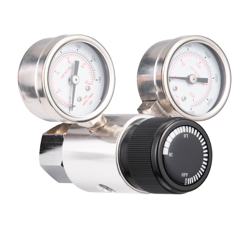
Jul 24, 2026
A gas regulator reduces high, unstable gas pressure from a cylinder, tank, or pipeline down to a steady, usable pressure for the equipment on the other end. It does not control flow rate directly; it controls delivery pressure, and flow follows from that pressure and the size of the downstream orifice. Without a properly sized gas regulator, appliances either starve for gas or receive dangerously excessive pressure, both of which shorten equipment life and create unsafe operating conditions. Every gas regulator relies on the same basic relationship: a sensing element measures outlet pressure, a loading mechanism (almost always a calibrated spring) sets the target pressure, and a control element (a valve and orifice) opens or closes to keep the two balanced. This is true whether the device is a small single-stage propane regulator on a barbecue or a multi-stage industrial gas regulator feeding a manufacturing line. The role of a gas regulator becomes clearer once the alternative is considered. Gas stored in a cylinder or delivered through a trunk pipeline is almost never at a pressure any burner tip, injector, or valve train is designed to accept directly. A propane cylinder, for example, can hold gas at pressure levels many times higher than what a residential stove burner needs. Feeding that pressure straight into an appliance would produce an uncontrolled flame, excess soot, or outright equipment failure. The gas regulator sits between the two, absorbing that difference continuously and silently, which is why most people never think about it until it fails. A second, less obvious function of a gas regulator is protecting downstream components from pressure spikes. Pipeline pressure is rarely perfectly constant; compressor cycling, valve switching elsewhere in the system, and temperature changes all cause small pressure surges. A correctly sized gas regulator absorbs these fluctuations before they reach sensitive downstream instrumentation, burners, or control valves, extending the service life of the whole system rather than just preventing a single point of failure. The internal process of a gas regulator can be broken into stages. Understanding this sequence makes it far easier to diagnose why a regulator is delivering too much, too little, or inconsistent pressure. High-pressure gas from a cylinder or supply line enters the regulator body through a sealed inlet connection. At this point, pressure can be anywhere from a few bar in a low-pressure pipeline to several hundred bar in a compressed industrial cylinder. The inlet connection is machined to a tight tolerance so that no gas escapes around the fitting itself, since even a small external leak at this stage defeats the entire purpose of pressure control further downstream. A valve seat and orifice restrict how much gas passes through at any moment. The size of the opening is not fixed; it changes continuously based on the position of the diaphragm above it. The orifice itself is often the single most application-specific part of a gas regulator, since its diameter determines the maximum flow the unit can physically pass regardless of how the spring is adjusted. A flexible diaphragm sits between the outlet chamber and a spring-loaded chamber. As outlet pressure rises, it pushes the diaphragm against the spring, closing the valve slightly. As outlet pressure falls, the spring pushes back, opening the valve further. This constant micro-adjustment is what keeps outlet pressure steady even when inlet pressure drifts. The diaphragm material itself matters: elastomer diaphragms are common in general service, while metal diaphragms are reserved for high-purity or corrosive gas regulator applications where elastomer permeation would contaminate the gas stream. Many gas regulator designs include an internal or supplementary relief valve that vents gas if outlet pressure climbs beyond a safe threshold, for example if the main valve seat fails to seal fully. This relief path is a secondary safeguard layered on top of the primary spring-diaphragm control loop, not a replacement for it. Once pressure is stabilized, gas leaves through the outlet port at the pressure the spring was set to deliver, whether that is 28 millibar for a domestic LPG appliance or several bar for an industrial burner. From here the gas typically passes through a final shutoff valve or solenoid before reaching the actual point of combustion or use. Gas regulators are grouped primarily by how many pressure-reduction stages they use and by the specialized service they are built for. Choosing the wrong category is one of the most common reasons a gas regulator underperforms or wears out early. Reduces pressure in one step. As the cylinder empties and inlet pressure drops, outlet pressure will drift slightly, a behavior known as supply pressure effect. Best where someone can periodically re-check the setting. Splits reduction into an intermediate stage (roughly three times the final working pressure) and a final stage, cancelling out most of the drift a single-stage unit shows. This makes two-stage gas regulators the standard choice for unattended or safety-critical lines. Built with metal diaphragms and specialized seats to minimize internal diffusion and contamination, or engineered specifically for reactive gases such as oxygen and acetylene where standard materials are unsuitable. An adjustable gas regulator has a knob or screw that changes spring tension, letting the operator dial in a different delivery pressure. A fixed or preset regulator is factory-set to a single pressure and cannot be changed, which reduces tampering risk on appliances designed for one specific pressure only. Nearly every gas regulator, regardless of type, is built from the same core set of functional parts. Recognizing them helps with both selection and troubleshooting. The main housing that contains and directs every other component; typically brass, aluminum, or stainless steel depending on the gas service. A flexible membrane that flexes with outlet pressure changes and transmits that motion to the valve mechanism. Provides the counter-force against the diaphragm and is what an adjustment knob actually changes when a delivery pressure is reset. Opens and closes the gas path in direct response to diaphragm and spring movement, the actual point where flow is throttled. Screens out particles and scale before they reach the seat, one of the most overlooked causes of premature regulator failure when neglected. The upper cap enclosing the spring chamber, often housing the adjustment screw and providing the mounting point for a vent or gauge port. An opening that allows the spring chamber above the diaphragm to breathe freely as the diaphragm moves, and doubles as a relief path if the internal relief mechanism opens. A threaded connection, often on both inlet and outlet sides, allowing a technician to fit a gauge and directly verify what pressure the gas regulator is actually delivering. Gas regulator specifications vary widely by application, but a few reference ranges help buyers sanity-check whether a unit is appropriately sized for their system. The same core mechanism scales from a small camping stove to a full industrial gas distribution manifold. A gas regulator shows up wherever pressurized gas needs to be brought down to a safe, workable level. Buyers frequently confuse a gas regulator with other flow-control hardware. Understanding the distinction avoids specifying the wrong part for a job. A shutoff valve is a binary on-off device; it has no ability to sense or hold a specific outlet pressure the way a gas regulator does. A relief valve only opens once a threshold is exceeded to vent excess pressure; it is not designed to continuously modulate flow to hold a steady working pressure. A flow control valve targets a specific flow rate regardless of pressure; a gas regulator targets a specific pressure, and flow is simply the result of that pressure meeting downstream demand. A gas valve simply opens or closes a gas path. A gas regulator actively senses outlet pressure and continuously adjusts an internal valve to hold that pressure steady, regardless of how the valve position needs to change to do it. Only if the internal materials, seals, and orifice are rated for each specific gas. Using a gas regulator outside its approved gas compatibility list is one of the most common causes of seal failure and leaks. This is the supply pressure effect. Single-stage regulators are more sensitive to it because they perform the full pressure reduction in one step; two-stage regulators largely cancel this effect out. There is no single fixed number, since service life depends heavily on cycle count, gas type, and environment. A regulator showing pressure creep, inconsistent delivery, or visible corrosion on the body should be evaluated for replacement regardless of age. Rapid pressure drop across the valve can cause localized cooling, and any moisture in the gas stream can freeze at the valve seat. This is more common with high flow demand on single-stage regulators in cold ambient conditions. Droop describes how much the outlet pressure falls as flow increases from zero to the regulator's maximum rated capacity. Lower droop means more stable delivery pressure under varying demand. Not necessarily. Two-stage regulators offer more stable outlet pressure, but single-stage units are simpler, more compact, and perfectly adequate where inlet pressure stays relatively constant and periodic adjustment is acceptable. It stops particles, scale, and debris from reaching the valve seat and diaphragm. A blocked or damaged filter is a frequent root cause of inconsistent outlet pressure and premature seat wear. Whistling or chattering usually points to diaphragm oscillation, often caused by running an oversized regulator at very low flow, where the valve hunts back and forth trying to hold a stable position. Adjusting a gas regulator changes outlet pressure, not the maximum physical flow capacity set by the orifice size. Increasing pressure can raise usable flow up to that physical limit, but it cannot exceed what the orifice and body are rated to pass. Lock-up pressure is the point at which the valve seat closes completely because there is no downstream demand, holding a slightly elevated static pressure until gas starts flowing again. The underlying principle is identical, but industrial gas regulators are typically built with more durable materials, higher flow capacity, and often a two-stage layout to handle continuous duty cycles that residential units rarely see.What a Gas Regulator Does
How a Gas Regulator Works
1
Gas Enters the Inlet
2
The Valve Meters the Flow
3
The Diaphragm and Spring Balance Pressure
4
A Relief Mechanism Guards Against Overpressure
5
Regulated Gas Exits to the Application
Main Types of Gas Regulators
Type
Stages
Best Suited For
Single-stage regulator
One
Stable inlet pressure, simple setups, occasional monitoring
Two-stage (dual-stage) regulator
Two
Fluctuating inlet pressure, continuous unattended operation
Line pressure regulator
One
Point-of-use pressure control on low-pressure pipelines
High-purity gas regulator
One or two
Semiconductor, laboratory, and analytical gas systems
Special service regulator
Varies
Oxygen, acetylene, corrosive gas, ultra-high-pressure service
Adjustable regulator
One or two
Test benches and systems needing frequent pressure changes
Fixed (preset) regulator
One
Appliances with one known, unchanging pressure requirement
Single-Stage
Two-Stage
High-Purity / Special Service
Adjustable vs Fixed
Key Components Explained
Body
Diaphragm
Spring
Valve Seat
Inlet Filter
Bonnet
Vent Port
Pressure Gauge Port
Typical Pressure Ranges and Performance Data
11 to 37 mbar Typical domestic LPG delivery pressure
Up to 300 bar Common inlet pressure for industrial cylinder service
3x Typical intermediate stage pressure vs. final delivery pressure in two-stage units
0.5 to 2 bar Typical delivery pressure range for small industrial burners
Term
Meaning
Droop
Drop in outlet pressure between zero flow and maximum rated flow capacity
Supply pressure effect
Change in outlet pressure caused purely by a falling inlet pressure as a cylinder empties
Lock-up pressure
Pressure at which the valve fully seats and stops flow at zero demand
Cv (flow coefficient)
A standardized number describing how much flow a regulator can pass at a given pressure drop
Response time
How quickly the regulator re-stabilizes outlet pressure after a sudden change in demand
Where Gas Regulators Are Used
Residential and Commercial
Mobile and Outdoor
Industrial and Technical
Agriculture and Specialty
Gas Regulator vs Related Devices
Gas Regulator
vs
Shutoff Valve
Gas Regulator
vs
Pressure Relief Valve
Gas Regulator
vs
Flow Control Valve
Choosing and Maintaining a Gas Regulator
Selection Checklist
Installation Tips
Maintenance Practices
Common Gas Regulator Problems and Likely Causes
Symptom
Likely Cause
Weak or fluctuating flame
Clogged inlet filter or undersized regulator for current demand
Pressure creeps up after shutoff
Worn or debris-fouled valve seat not sealing fully
Frosting on the regulator body
High flow demand combined with cold ambient temperature and moisture in the gas
Audible whistling or chattering
Diaphragm oscillation, often from an oversized regulator running at very low flow
Outlet pressure drops under load
Regulator undersized for peak flow, high droop, or falling inlet pressure
Frequently Asked Questions
What is the difference between a gas regulator and a gas valve?
Can one gas regulator work with different types of gas?
Why does my gas regulator's output pressure drop as the cylinder empties?
How often should a gas regulator be replaced?
What causes a gas regulator to freeze up in cold weather?
What does droop mean on a gas regulator specification sheet?
Is a two-stage gas regulator always better than a single-stage unit?
What is the purpose of the inlet filter in a gas regulator?
Why does a gas regulator sometimes make a whistling noise?
Can a gas regulator be adjusted to increase flow?
What is lock-up pressure on a gas regulator?
Do industrial and residential gas regulators use the same internal design?
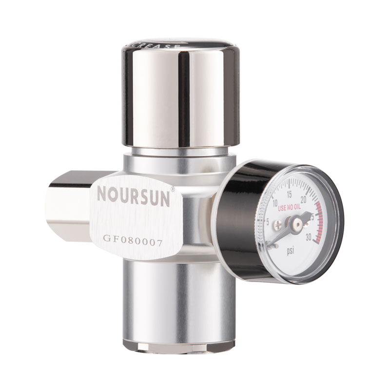
Mar 31, 2026
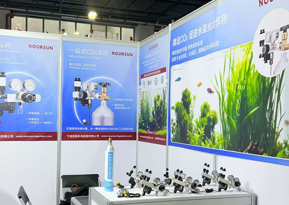
NOURSUN will participate in Interzoo 2026, held at the NürnbergMesse Exhibition Center from May 12 to 15, 2026. As one of the most influential trade shows in the global pet supplies industry, Interzoo is a vital platform for companies to expand into international markets and establish partnerships.
At this exhibition, NOURSUN will showcase its latest technological achievements in the aquarium equipment sector at Booth 12.0-478C, with a focus on new CO2 regulators and comprehensive CO₂ system solutions for planted aquariums to meet diverse needs ranging from professional aquascaping to consumer-grade aquarium applications.
Leveraging Interzoo as an international exchange platform, NOURSUN will further deepen communication with global customers, actively seize industry development opportunities,and enhance the brand’s competitiveness in the global aquarium equipment market.
Looking forward to meeting you in Nuremberg!

Dec 05, 2025
From December 3 to 5, 2025, NOURSUN successfully participated in the Drink JAPAN 2025 exhibition held in Makuhari, Japan. As the most influential event in the Asia-Pacific region for beverage and liquid food development and manufacturing technologies, this exhibition provided NOURSUN with a valuable platform for in-depth exchanges with global industry peers.
During the event, NOURSUN showcased its latest range of pressure regulators for the beer dispensing and sparkling water sectors. Booth [5-11] attracted numerous industry professionals who stopped to visit. NOURSUN team engaged in in-depth discussions with existing and new clients from around the world. On-site product demonstrations received positive feedback, further solidifying existing partnerships and opening up multiple potential new opportunities.
Drink JAPAN 2025 provided NOURSUN with a significant opportunity to enhance its international brand influence. Moving forward, NOURSUN will continue to uphold its professional ethos and collaborate with global partners to jointly drive technological progress and value creation within the industry.
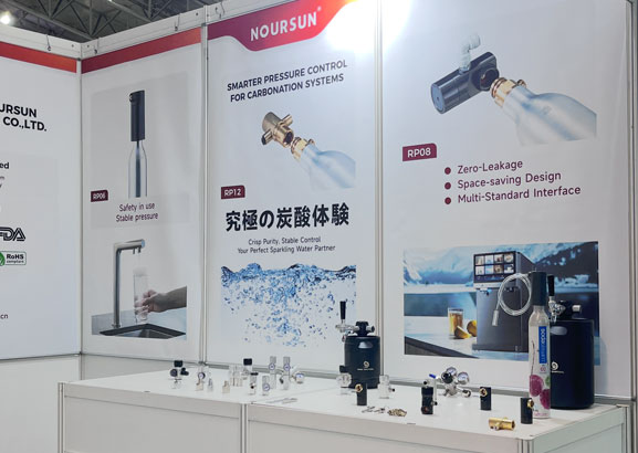
Nov 13, 2025
From November 13 to 16, 2025, NOURSUN successfully participated in the China International Pet & Aquarium Show (CIPS 2025) held in Guangzhou. As one of the world’s top three pet and aquarium trade shows, CIPS brings together manufacturers and suppliers from around the globe, providing NOURSUN with an excellent platform to showcase its innovative achievements and deepen industry exchanges. During the exhibition, NOURSUN made a spectacular debut with its brand-new series of pressure regulators for the aquarium industry. Booth [13.1-C071] attracted numerous professional visitors. The NOURSUN team engaged in in-depth discussions with existing and new clients as well as industry partners from around the world. On-site product demonstrations garnered widespread attention and positive feedback, further solidifying existing partnerships and opening up multiple potential opportunities for collaboration. Through this exhibition, NOURSUN has further strengthened its close ties with industry peers and clarified the direction for continued innovation in the aquarium sector.
ADD: No. 50, Zhongxing East Road, Xikou Town, Fenghua District, Ningbo City, Zhejiang Province, P.R. China
0086-574-88881358
0086-574-88473625
About Us
Industry Applications
News & Events
