
 简体中文
简体中文
 English
 Français
 日本語
日本語
 Deutsch
0086-574-88881358
0086-574-88473625


News
Sep 14, 2026
Choosing a gas pressure regulator is not a one-size-fits-all decision. You can narrow the search quickly by answering six questions: what gas are you regulating, what is your inlet pressure, what outlet pressure do you need, how much flow must the regulator deliver, how stable must that delivery stay, and what environment will it live in? Once you have those answers, you can pick a regulator that will not creep, surge, or fail prematurely. Below, we break down each factor with real numbers and product examples so you can make a confident choice. Different gases behave differently across pressure ranges. CO2, for example, can transition from a liquid to a gas inside a cylinder as the temperature changes, which means an unheated regulator can freeze and drop its delivery pressure. Argon is stable but heavier, while compressed air contains moisture that can corrode internal parts if the regulator is not built for it. Your first move is to confirm the gas name, the cylinder pressure at full charge, and whether the cylinder is a high-pressure (2000–3000 psi) or low-pressure (around 300 psi) type. For a soda water system running on CO2, a regulator with a brass body and a stainless steel seat is a safer bet because it resists the moisture that accompanies CO2 expansion. A purpose-built CO2 unit keeps outlet pressure steady even as the cylinder drains, so you avoid inconsistent carbonation levels between bottles. If you work with compressed air, look for an internal filter or a separate moisture trap. For nitrogen or argon, the regulator can be lighter and more compact, but always confirm that the inlet fitting matches your cylinder valve. A mismatch here will cost you a return shipment and downtime. Determine the target outlet pressure. For draft beer, that is usually 12 to 15 psi; for home sparkling water, it can range from 30 to 45 psi; for aquarium CO2, 20 to 30 psi is typical; for paintball tanks, the regulator may need to handle up to 3000 psi inlet and deliver 800 psi to the marker. The lower the operating pressure, the more important the regulator's low-pressure accuracy becomes. Single-stage regulators are simpler but they output a higher pressure when the cylinder is fresh and lower pressure when it is nearly empty. The difference can be 2–3 psi on a 30 psi setpoint, which is enough to affect carbonation or dosing. If your process tolerates no more than 0.5 psi of drift, you need a dual-stage regulator. For a dual-stage unit, the first stage drops the incoming pressure to an intermediate level (often around 250–400 psi), and the second stage delivers the precise setpoint. This arrangement keeps the outlet almost rock-solid from a full cylinder to the last shot of gas. Flow rate is often the most underestimated factor. A regulator can have perfect pressure control at 0.1 cubic feet per minute but starve your equipment at 1.0 CFM. Match the regulator's maximum flow capacity to your highest instantaneous demand. Undersizing leads to pressure drop at the moment of draw, which causes flat beer or weakly carbonated water. When you compare models, ask for the rated CFM at the outlet pressure you plan to use, not just the maximum inlet pressure. Also check the regulator's Cv value if the manufacturer publishes it. A higher Cv indicates a larger internal passage and a better ability to handle surges. Pressure stability is what separates a good regulator from a great one. Look for a regulator with a diaphragm that responds quickly to changes in outlet demand, and a spring that is designed for the specific outlet range. Do not use a 100 psi spring to deliver 12 psi—the adjustment will be coarse and unreliable. A dual-gauge regulator shows both cylinder pressure and delivery pressure, which lets you know how much gas is left and whether the outlet is holding steady. For aquarium applications, a 0–50 psi delivery gauge is ideal; for draft beer, a 0–30 psi gauge is easier to read at a glance. A built-in manometer is particularly useful when you are running a dual-stage regulator, because you can instantly see the intermediate pressure and the output pressure. This diagnostic capability saves time when you are tuning a new installation or troubleshooting a system that is not performing as expected. Materials affect both durable life and gas compatibility. For dry gases like argon, a zinc alloy or aluminum body works well. For CO2 with the risk of condensation, brass or stainless steel wetted parts are more reliable. For food and beverage environments, avoid regulators with oil-based lubricants in the path of the gas. Connection size and thread type are just as important. Common regulators use 1/4 inch NPT or BSP, while the cylinder connection may be CGA-320, CGA-580, or DIN. Always take a photo of your existing cylinder and regulator connection before ordering. Mismatched threads are the number one cause of regulator returns. Where the regulator sits matters. In a home carbonation cabinet, look for a compact regulator that fits under the counter. In a brewery, you might need wall-mounted brackets. In an aquarium room, humidity can corrode gauges, so choose a regulator with a sealed gauge. In a paintball tank bag, the regulator should be shock-resistant and light. A good example is a mini CO2 regulator, which is engineered for small spaces like soda makers and beverage dispensers. It gives you the same pressure control in a footprint that fits neatly inside a kitchen cabinet or a product enclosure. For a full view of how these regulators are applied in a range of settings, you can look at our application pages. If the regulator will be exposed to vibration, tighten the adjustment screw with a locking nut or use a model with a locking feature. If it will operate in a hot environment, verify that the diaphragm material can handle the temperature at full load. Single-stage and dual-stage regulators solve different problems. A single-stage regulator reduces cylinder pressure to delivery pressure in one step. It is compact and inexpensive, but its outlet pressure changes as the cylinder empties. A dual-stage regulator uses two internal stages: the first stage drops high pressure to an intermediate pressure, and the second stage precisely controls the output. If you have multiple regulators on the same high-pressure line, ensure that each regulator has sufficient upstream pressure to feed the first stage. A die-cylinder regulator may operate from 300 psi to a full 2000 psi, but a low-pressure line will not. Always check the minimum inlet pressure specification. Three mistakes cause most regulator problems: The cost of these mistakes can be measured in product waste, setup time, and replacement parts. A single miscalculated CO2 system in a bar can waste a full keg of beer every week when the pressure drifts by 3 psi. In an aquarium, the same drift may cause pH fluctuations that stress fish and plants. Before you buy, request the regulator's performance curve. Look for data on outlet pressure across the inlet range, hysteresis, and temperature behavior. Run a simple leak test with soapy water on the connections. Verify that adjustment screws are stable and do not creep under vibration. A good supplier will explain the limit of the diaphragm and the recommended service intervals. For a B2B relationship, it is also useful to ask how the factory handles custom fittings and whether they offer pilot samples. You can learn more about our engineering background on our About page. If the regulator will be used for a craft beverage application, ask about the internal smoothness and whether the factory performs a 100% leak check before shipment. Also, ask how the regulator's performance changes after 50,000 cycles, because that is often where a low-quality spring will begin to shift. Once you have defined the six variables above, you can map them to the existing product family: This map is only a starting point. In practice, every installation has its own quirks, and an engineered solution often involves adjusting a standard regulator's spring range, gauge scale, or inlet fitting. That is why it is better to talk with someone who understands the real-world behavior of gas pressure rather than simply matching a model number. A single-stage regulator reduces the full cylinder pressure to the delivery pressure in one step. A dual-stage regulator does it in two steps. The dual-stage design maintains a more constant outlet pressure as the cylinder empties, which is critical for processes that cannot tolerate pressure drift. Most home sparkling water makers operate between 30 and 45 psi. Commercial systems may run at 50 psi or higher. Check the manufacturer's recommendation for your specific machine, and always choose a regulator that can be adjusted precisely within that range. When CO2 expands through the regulator, the gas temperature drops rapidly. If the ambient humidity is high, moisture can condense and freeze on the regulator body. Moving to a dual-stage regulator or increasing the distance between the cylinder and the regulator can reduce freezing because the pressure drop is spread over two stages. Generally yes, because both are inert gases and do not react with common regulator materials. However, you must verify the inlet connection and the pressure rating. Nitrogen cylinders often use a different valve than argon, so the regulator inlet fitting must match the cylinder model. The most common tool-side connection is 1/4 inch NPT or 1/4 inch BSP. The cylinder-side connection depends on the gas and the country, with common options being CGA-320, CGA-580, and DIN. Always confirm both ends before placing an order. No matter what you regulate, the same decision framework will help you choose. Start with the gas, define the pressures, calculate the flow, verify stability, check materials, and match the environment. If you have questions about a specific application, a quick conversation with an engineering team will save you weeks of trial and error.Start with the Gas Type and Its Inlet Condition
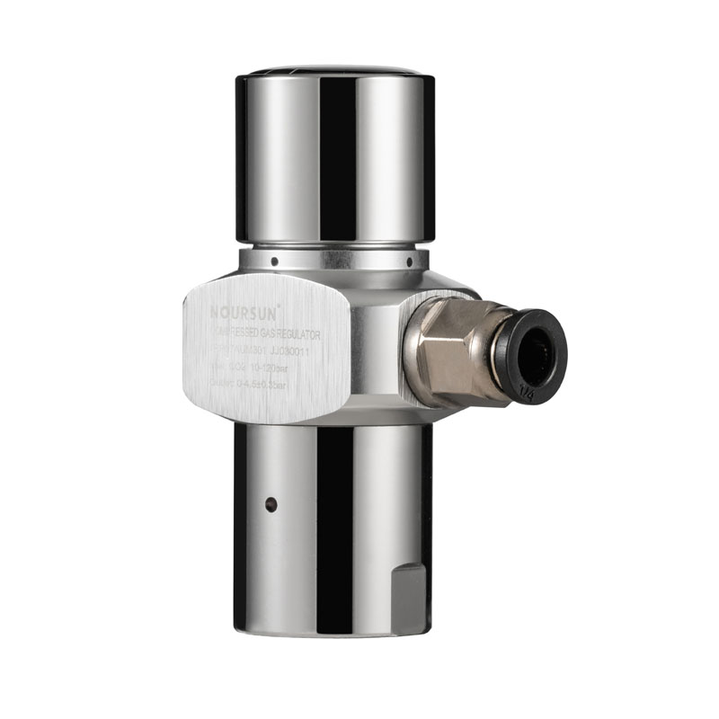 Soda Water CO2 Regulator for Consistent CarbonationThis regulator is designed for household carbonation systems, letting you precisely adjust output pressure for preferred fizz levels. Its internal relief and sealing-before-opening mechanisms ensure safe, efficient gas use in compact installations.View Product →
Define the Pressure Range and Outlet Setpoint
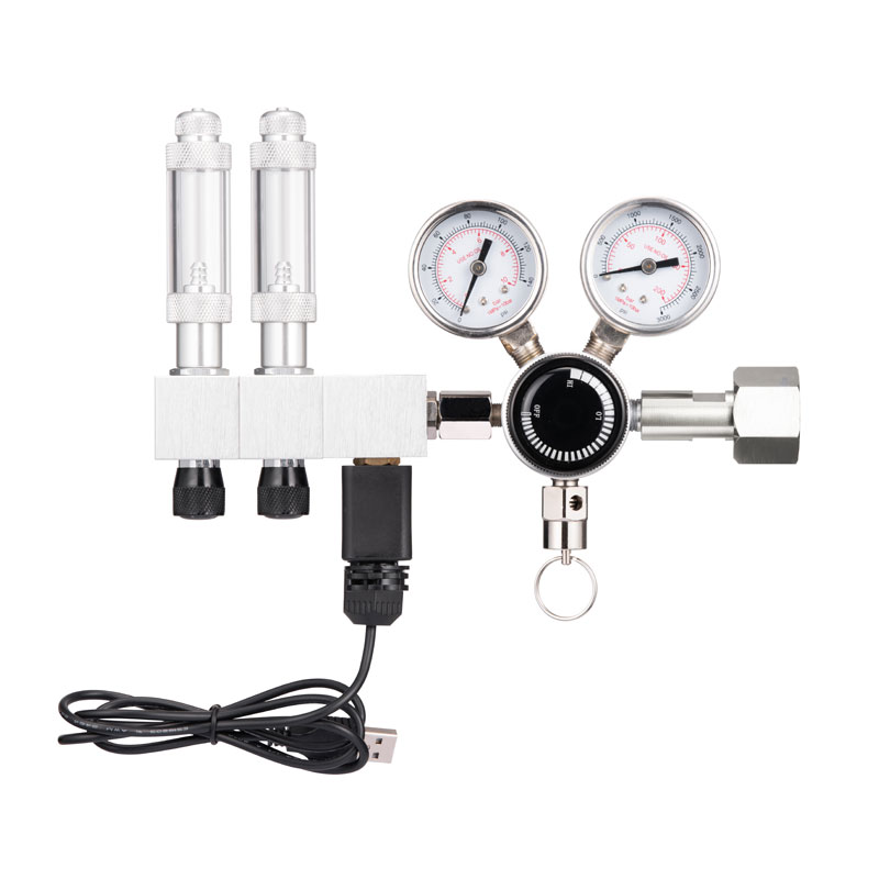 Dual Stage CO2 Regulator with Manometer for AquariumsA two-stage regulator with dual gauges, relief valve, and bubble counter, compatible with multiple cylinder standards. It delivers stable pressure and precise bubble output, making it ideal for planted tanks and greenhouses.View Product →
Match the Flow Rate to Your Equipment's Demand
Evaluate Pressure Stability and Gauge Visibility
Choose the Right Materials and Connection Style
Material
Best For
Cost
Maintenance
Brass
CO2, argon, air
Moderate
Occasional cleaning
Stainless Steel
Most gases including wet CO2
Higher
Minimal maintenance
Zinc Alloy
Argon, dry air
Low
More frequent surface inspection
Think About the Application Environment
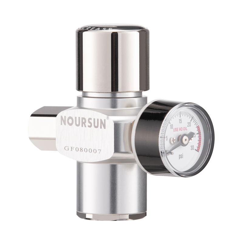 Mini CO2 Regulator for Portable Kegs and DispensersCompact and lightweight, this regulator fits small kegs and cartridges for beer or soda dispensing. It provides steady pressure and flow, minimizing foam, and offers adjustable output with optional gauge and cartridge holder.View Product →
Single-Stage vs. Dual-Stage Regulators
Feature
Single-Stage
Dual-Stage
Output Drift
2–3 psi typical
Less than 0.5 psi
Cost
Lower
Higher
Size
Compact
Larger
Best For
Manual beer dispensing, non-critical
Carbonation, aquarium, precision dosing
Common Selection Mistakes and Their True Cost
How to Validate a Regulator Before You Buy
How Noursun's Product Lineup Helps You Narrow the Choice
Frequently Asked Questions About Choosing a Gas Pressure Regulator
What is the difference between a single-stage and a dual-stage regulator?
How do I know what outlet pressure my soda water system needs?
Why does my CO2 regulator freeze up?
Can I use an argon regulator for nitrogen?
What size connections do most regulators use?

Sep 07, 2026
A back pressure regulator (BPR) maintains a pre-set pressure in the line upstream of the valve by modulating flow on a continuous basis. A relief valve opens only when system pressure exceeds a pre-set limit and vents fluid or gas to prevent overpressure. The core difference is function: one is a control device, the other is a protective device. This is why the two are not interchangeable, even though both respond to pressure. A back pressure regulator works to keep pressure at a working point, such as 35 psi, by slowly opening and closing in response to load changes. A relief valve sits idle at 35 psi, then snaps open when a pressure spike pushes it past its setpoint, and reseats once the danger clears. Choosing the wrong one produces a different set of failures. Use a relief valve where a back pressure regulator is needed, and process pressure will drift, affecting pump performance, spray density, or gas blanketing. Use a back pressure regulator where a relief valve is needed, and there is no safety margin if upstream pressure rises beyond the equipment rating. This guide walks through how each device works, where they apply, and how to know which one your system requires. Learn more about Noursun's pressure control expertise. A back pressure regulator is a pressure control valve that maintains a constant pressure on its inlet side. It does this by creating a controlled restriction to flow. If the upstream pressure tries to rise above the setpoint, the valve opens wider to allow more flow through, which brings the pressure back down. If the upstream pressure drops below the setpoint, the valve throttles closed, building pressure back up. In practice, a BPR is typically installed downstream of the pressure source, such as a pump, a gas cylinder, or a reactor vessel, and it holds pressure in the segment of pipe just before it. Because of this, the BPR is sometimes called a pressure holding valve or a backhold regulator. The BPR uses a spring chamber as the internal reference. The spring force is set to a specific value and opposes the upstream pressure acting on the valve diaphragm. When upstream pressure exceeds the spring force, the diaphragm is pushed upward and the valve opens. When upstream pressure drops, the spring pushes the diaphragm back down and the valve closes. This cycle of micro-adjustments maintains the desired pressure. Common applications for back pressure regulators include: A relief valve is an automatic safety device that opens to release fluid or gas when the pressure in a system exceeds a pre-set limit. It is normally closed and stays closed during normal operation. When pressure rises to the setpoint, the valve opens and vents the excess pressure through a discharge port. It reseats once the pressure returns to a safe level. The function of a relief valve is entirely different from that of a back pressure regulator. A relief valve is not designed to throttle flow or maintain a process setpoint. It is designed to protect the system from overpressure damage. Its job is simple: open when required, relieve, and close when the condition has passed. The spring in a relief valve pushes the disc or poppet onto the seat. System pressure pushes in the opposite direction. When system pressure becomes high enough to overcome the spring force, the disc lifts off the seat and excess pressure is released. The valve is sized so that its opening performance is quick, with the disc moving from closed to full lift in a matter of milliseconds for most designs. A key performance parameter of a relief valve is its blowdown, which is the difference between the pressure at which the valve starts to open and the pressure at which it fully reseats. Typical applications for relief valves include: The two devices come from different engineering philosophies. One is born from process control requirements, the other from safety considerations. The table below summarizes the most practical distinctions. The fastest way to tell the two apart is to ask: does this component actively hold a pressure setpoint while the process runs, or does it wait for an abnormal condition and then open? If the first, it is a back pressure regulator. If the second, it is a relief valve. A back pressure regulator is designed to be in continuous motion. Its diaphragm and spring are constantly rebalancing as the system load changes. In a well-sized BPR, the deviation from the setpoint will be small. For example, a high-quality regulator might maintain its setpoint within 1 percent of full scale, even as the flow rate varies over a 10:1 turndown range. This characteristic is what makes a BPR appropriate for processes where pressure stability is directly tied to production quality. In a spray coating application, a 2 psi variation in nozzle pressure can alter droplet size distribution. A BPR prevents that variation from occurring. A relief valve is designed to be binary in its behavior: mostly closed, and then fully open. The transition happens quickly, in a time frame that can be less than 50 milliseconds for small gas systems, because the technology relies on a spring-loaded disc that lifts off its seat once pressure force overcomes the spring constant. After the relief event, the valve does not close at the same pressure as it opened. It resets at a lower pressure. This difference is blowdown, and for most spring-loaded relief valves it falls in the range of 10 to 15 percent of set pressure. If a valve is set at 100 psi, it might open at exactly 100 psi and reseat at about 85 to 90 psi. This gap exists to prevent the valve from rapidly cycling or chattering when the pressure is right at the setpoint. The blowdown provides a margin of stability. If your requirement is to maintain a constant operating pressure in a line, a back pressure regulator is the correct component. This applies to any scenario where upstream pressure fluctuates and the process depends on that pressure being held steady. Pump discharge pressure control, tank blanketing pressure, and gas header pressure stabilization all fall into this category. If your requirement is to prevent equipment from being damaged by overpressure, a relief valve is the correct component. This applies to pressure vessels, heat exchangers, piping, and any component whose maximum allowable working pressure could be exceeded during a process upset. A relief valve is a safety measure, not a control measure. In many real systems, both devices are present and perform separate roles. A typical CO2 beverage line might have a pressure-reducing regulator at the cylinder, a back pressure regulator to stabilize pressure at the carbonation point, and a relief valve downstream of the pressure-reducing regulator to protect the line if the regulator fails. This arrangement demonstrates that control and protection are complementary functions. For many gas delivery applications, especially where pressure needs to be reduced from a cylinder to a working pressure, a pressure-reducing regulator is used instead of a back pressure regulator. This is because the task is to maintain a constant downstream pressure rather than upstream pressure. Explore Noursun's application guides to see how pressure-reducing regulators are used across beverage, hydroponics, and industrial gas systems. Engineers and technicians often confuse the two for understandable reasons. Here are the most common misconceptions. It does not. A relief valve only sets the maximum pressure that a system can tolerate. It does not hold a process pressure at a setpoint. If you want pressure maintained at 40 psi, you need a back pressure regulator or a pressure-reducing regulator, not a relief valve set at 40 psi. The relief valve will not act until pressure exceeds 40 psi, which means the process pressure will be uncontrolled below that point. A BPR can provide some protection in a limited sense, but it is not engineered for the snap-action response that a relief valve provides. The BPR will slowly open as pressure rises, but a slow opening may not provide adequate protection against a positive displacement pump deadhead or a thermal expansion scenario. A relief valve is the only device intended for that specific job. They cannot be swapped. As a control device, the BPR holds a setpoint. As a safety device, the relief valve protects against overpressure. Selecting one based on availability or cost is a common reason for system failures. Not as a primary safety device. A BPR is designed to modulate flow in response to pressure changes. A relief valve is designed to provide rapid overpressure protection. The BPR could theoretically open at a higher pressure, but it is not engineered with the same opening speed, discharge characteristics, or re-seat behavior that safety applications require. If you need overpressure protection, install a relief valve. A relief valve can go from closed to full open in under 50 milliseconds because its spring is sized to snap open once the setpoint is exceeded. A back pressure regulator moves gradually and proportionally, taking several seconds to reach a new equilibrium after a flow rate change. Most CO2 beverage systems use a pressure-reducing regulator to bring cylinder pressure down to a working pressure, typically 30 to 45 psi. A back pressure regulator may be added to maintain a stable pressure at the carbonation point. A relief valve is often installed as protection if the pressure-reducing regulator fails. If you are setting up a new system, check what your equipment manufacturer calls for. For the pressure-reducing role, Noursun offers CO2 regulators designed for soda and beer dispensing systems. Often yes. The two serve distinct roles. The BPR helps keep process pressure steady during normal operation. The relief valve protects the system against abnormal spikes. Many well-designed gas and liquid systems include both to achieve both control and protection. Blowdown is the pressure difference between when a relief valve opens and when it reseats. If set pressure is 100 psi and reseat pressure is 90 psi, the blowdown is 10 percent. This margin prevents the valve from rapidly cycling. Without it, a relief valve could open and close repeatedly, which is called chatter, and this can damage the valve seat. For a back pressure regulator, size it based on the flow rate range it must control and the acceptable pressure deviation. For a relief valve, size it based on the maximum overpressure flow that must be relieved, and confirm that the valve can pass that flow without the pressure rising beyond the equipment's maximum allowable working pressure. The back pressure regulator and the relief valve are related concepts and are often discussed together, but they are not interchangeable. A back pressure regulator maintains a set pressure through continuous modulation. A relief valve protects system components from dangerous overpressure by opening only when needed. The quickest way to remember the difference is this: the back pressure regulator holds the process in a comfortable band, and the relief valve cuts in only during a spike. If you can say which one you need and why, you are most of the way to a properly designed pressure control system. Noursun Regulators is a manufacturer of gas pressure control components and has been producing pressure regulators since 2012, serving industries such as beverage dispensing, hydroponics, and soda systems. Their product range includes CO2 pressure regulators, aquarium regulators, and safety valves for industrial and consumer applications.Back Pressure Regulator vs Relief Valve: The Direct Answer
What Is a Back Pressure Regulator?
What Is a Relief Valve?
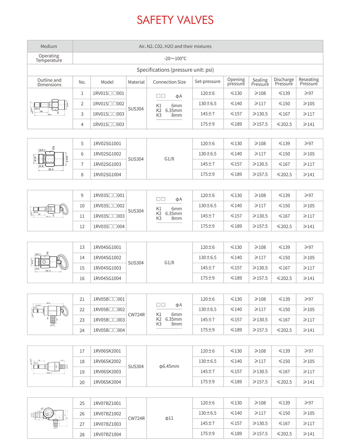 Custom Safety Valve for Pressure Relief and System ProtectionExplore how safety valves are rated and matched to system requirements, ensuring reliable overpressure protection in gas, liquid, and mixed-phase applications.View Product →
Key Differences Between Back Pressure Regulator and Relief Valve
Parameter
Back Pressure Regulator
Relief Valve
Primary function
Maintains a constant upstream pressure
Relieves excess pressure for protection
Normal operating state
Continuously modulating
Normally closed
Flow behavior
Throttles flow proportionally
Snaps open then reseats
Response time
Slow to moderate
Very fast
Setpoint behavior
Holds setpoint across changing loads
Activates only above setpoint
Typical location
Downstream of the pressure source
On the vessel or line needing protection
Failure philosophy
Controls within an operating envelope
Provides a last line of defense
Common value driver
Precision and turndown ratio
Setting accuracy and repeatability
How Each Device Behaves in Real Operating Conditions
Back Pressure Regulator Performance Characteristics
Relief Valve Performance Characteristics
When to Use Each Device
Custom Soda Water CO2 Regulator for Carbonation ControlLearn how this regulator precisely adjusts output pressure for consistent carbonation, with safety features and compact design suited for household and commercial use.View Product →
Key Selection Factors
Common Misconceptions and Selection Pitfalls
Misconception 1: A relief valve maintains system pressure
Misconception 2: A back pressure regulator provides overpressure safety
Misconception 3: Either component can be used for pressure control
Frequently Asked Questions
Can a back pressure regulator be used as a relief valve?
What is the main difference in response time?
Which one do I need for a CO2 beverage dispensing system?
Do I need both a back pressure regulator and a relief valve in the same system?
What is blowdown and why does it matter?
How do I size these valves?
Final Takeaway
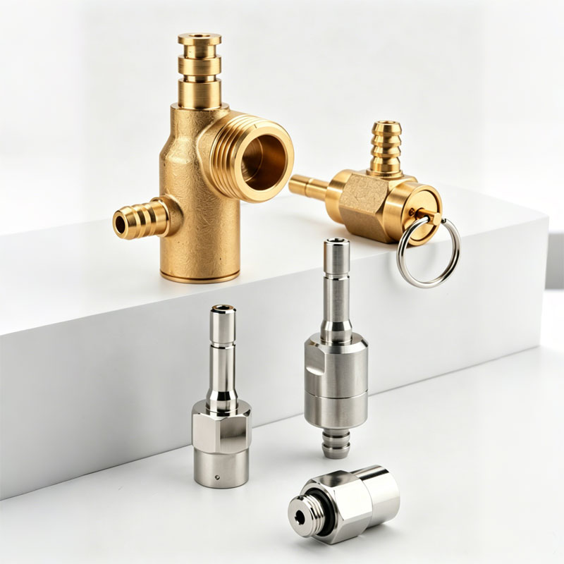
Aug 31, 2026
At 20°C, a full CO2 cylinder can hold about 830 psi (57 bar). Your soda line may need only 30 psi. Connect the two directly and you are asking for leaks, failed seals and inconsistent carbonation. A step down gas regulator prevents this by taking high, variable cylinder pressure and delivering a stable, usable lower pressure. The name describes the function exactly: it steps the pressure down. It does not simply throttle gas. A true regulator senses downstream pressure and makes tiny adjustments to keep the outlet pressure at the set value, whether the cylinder is nearly full or almost empty. That is why a small beverage machine, a hydroponic CO2 dosing system, and a paintball tank all rely on the same core component in different sizes and pressure ranges. The working principle is mechanical and reliable. Four main parts carry out the pressure control: When you turn the knob clockwise, the spring pushes the diaphragm down, which opens the valve further and lets more gas through. This raises the outlet pressure. Turning the knob counter-clockwise reduces spring force, allows the valve to close slightly, and lowers the outlet pressure. In a well-designed step down gas regulator, this happens continuously so that a steady downstream pressure is maintained. The biggest decision when choosing a step down gas regulator is whether to use one reduction stage or two. A single-stage regulator reduces cylinder pressure directly to the working pressure. A dual-stage regulator uses a first stage to bring the cylinder pressure down to an intermediate level, then a second stage to control the final outlet pressure. For applications that need precision and consistent output as the cylinder empties, dual-stage is usually the better choice. If you can accept a small variation in outlet pressure as the cylinder empties, a single-stage regulator may save money. If you run a system where production or product quality depends on a fixed pressure, a dual-stage design is worth the additional cost. There is no universal gas regulator. The right unit depends on the gas, the pressure range, the flow rate and the downstream equipment. Noursun builds regulators for several common gas control scenarios, and this section covers the main families. Bars, restaurants and home soda makers use CO2 pressure to carbonate water and push drinks through lines. A compact device such as the RP02 mini CO2 regulator is suited to this kind of duty because it can deliver a steady CO2 supply without taking up much space. In a complete soda system, a check valve and safety valve should be included so liquid cannot travel back into the regulator and cause corrosion or over-pressurization. Aquarium plants and hydroponic crops need controlled CO2 enrichment. Too much CO2 can stress fish or change nutrient uptake. A low-flow regulator with fine adjustment is essential. The RP23 aquarium CO2 regulator is an example of a regulator designed for this lower-flow, more sensitive application. The ability to set a precise bubble rate matters more than raw flow capacity. Argon, nitrogen and other inert gases are used for shielding, keg purging and other technical tasks. These gases have different cylinder pressures and fitting standards, so the regulator must match the gas service. For a stable delivery pressure that does not drift as the cylinder depletes, consider a dual-stage model like the RP04 dual-stage argon regulator. It is built to handle a higher-pressure inlet and provide a consistent outlet for a wide range of industrial and beverage workflows. A regulator is not a generic fitting. It must be chosen from the gas, the inlet pressure, the required outlet pressure and the flow demand. Working through these factors will prevent the common mismatch between a regulator and its equipment: If you have a specific flow target or an unusual fitting, Noursun's application engineering team can review the system and suggest the correct regulator configuration. This is especially useful for OEM projects where a standard catalogue product needs a different set point or a custom inlet connection. A step down gas regulator is a precision mechanical component, but it will not stay precise if it is installed poorly or ignored. The following routine is simple enough for a shift operator and thorough enough for a maintenance department. If you notice that the outlet pressure is climbing after the regulator has been sitting idle, the seat may be worn. In that case, stop use and replace the affected parts before it causes a downstream relief valve to open. Most regulator failures are not random. They come from repeated misuse. If you avoid these errors, the regulator will hold its performance much longer: It reduces a high-pressure gas supply to a lower, stable working pressure. It also maintains that pressure as the cylinder pressure decreases, so the downstream equipment sees a consistent supply instead of a gradual decline. The words are often used interchangeably. A pressure reducing valve is the broader category, while a step down gas regulator emphasizes the controlled reduction and ongoing regulation of pressure in a gas system. When CO2 expands through the regulator, the gas absorbs heat from the surrounding metal and moisture can freeze on the body. This is more common at high flow rates or when the gas contains moisture. Reducing the flow, using a higher-purity gas supply, or locating the regulator in a warmer area can help. No. Different gases require different connection standards, seal materials and pressure ratings. A regulator intended for argon should not be used with CO2 unless it is explicitly designed and rated for that service. Having a dedicated regulator for each gas is the safest and most reliable practice. There is no fixed universal interval. Inspect the regulator at least once a year, check for creep, listen for hissing, and verify that the outlet gauge holds steady. Replace the seat, diaphragm or the full regulator when the output pressure becomes erratic or continues to creep after adjustment. Regulator selection is not a commodity purchase. The difference between a regulator that drifts and one that holds pressure shows up in product quality, gas consumption and downtime. Noursun has focused on gas pressure control since 2012. According to the company profile, it invests roughly 7% of annual revenue in R&D and holds more than 35 patents in pressure control technology. That level of focus matters when you need a reliable, repeatable gas delivery system. If a standard step down gas regulator does not match your pressure range, flow demand or connection layout, send the gas type, working pressure and fitting details to Noursun directly. Custom engineering is a normal step for OEMs and integrators, and starting with those numbers usually produces a cleaner, cheaper solution than adjusting the system around an off-the-shelf part.A Pressure Problem That Needs a Step Down Gas Regulator
How a Step Down Gas Regulator Works
Single-Stage vs Dual-Stage: Which One Do You Need?
Factor
Single-Stage
Dual-Stage
Reduction steps
One
Two
Outlet pressure stability
Changes as cylinder pressure drops
Stable until the cylinder is nearly empty
Typical applications
General shop use, low-flow systems
Beverage dispensing, laboratories, precision CO2 dosing
Cost
Lower
Higher
Step Down Gas Regulator Types by Application
Beverage and carbonated water systems
Mini CO2 Regulator Manufacturer, Beer Keg Pressure Regulator SupplierNoursun Industrial Co., Ltd is China mini CO2 regulator manufacturer and beer keg pressure regulator OEM/ODM supplier, We custom and whol...View Product →
Aquarium and hydroponic systems
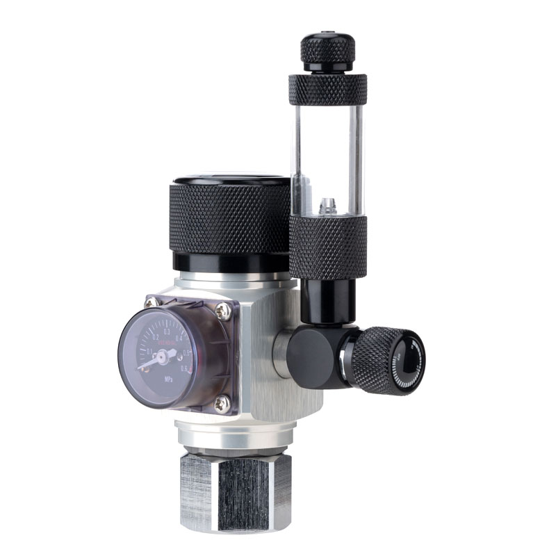 Custom Aquarium CO2 Regulator Manufacturer, OEM/ODM SupplierNingbo Noursun Industrial Co., Ltd is China aquarium CO2 regulator manufacturer and best co2 regulator for aquarium OEM/ODM supplier, We ...View Product →
Specialty and inert gas applications
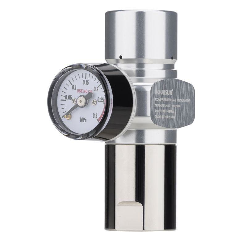 Dual Stage Argon Regulator Manufacturer, Dual Gas Regulator SupplierNingbo Noursun Industrial Co., Ltd is China dual stage argon regulator manufacturer and double gas regulator OEM/ODM supplier, We special...View Product →
How to Select a Step Down Gas Regulator
Installation and Maintenance Best Practices
Common Mistakes That Damage a Step Down Gas Regulator
Frequently Asked Questions
What does a step down gas regulator actually do?
Is a step down gas regulator the same as a pressure reducing valve?
Why does my CO2 regulator ice up?
Can I use one regulator for multiple gases?
How often should I replace a gas regulator?
Why a Specialist Supplier Matters

Aug 24, 2026
A gas pressure regulating valve (PRV) is a mechanical device that takes high, fluctuating inlet pressure from a gas cylinder or supply line and reduces it to a steady, adjustable outlet pressure. In any gas system, it is the single component that decides whether the equipment downstream receives a consistent supply or an unpredictable one. If you are selecting a PRV for a new project, the conclusion you need first is this: choose the regulating valve based on outlet pressure range, flow capacity, and inlet connection, in that order of priority. Consider the most common setup in beverage dispensing: a full CO2 cylinder at roughly 850 psi feeds a line that needs 35 psi. Without a pressure regulating valve, opening the cylinder valve sends the full 850 psi into the tubing, fittings, and solenoid. The result is a foamy pour, a leaking connection, and a carbonation level that changes from one glass to the next. The PRV sits between the source and the application, absorbs the cylinder pressure, and holds the line at the pressure you set. Note that the same abbreviation, PRV, is used in some industries for pressure relief valves, which vent gas to protect equipment. In gas control work, PRV normally refers to the pressure regulating valve, also called a pressure reducing regulator. This article covers the regulating type: how it works, how to choose one, and where it is used. A gas PRV works on a simple feedback principle. It monitors its own outlet pressure, compares that pressure with the force set by the adjusting spring, and then opens or closes a valve seat to correct any difference. This correction loop runs continuously, which is why the outlet pressure stays stable even as the cylinder pressure falls from full to nearly empty. Every gas pressure regulating valve, whatever the brand or size, is built around the same three elements: Understanding the pressures involved helps you read any specification sheet with more confidence. Here are realistic starting points for common gas PRV uses: Droop is the drop in outlet pressure you will see as flow increases. It happens because flowing gas pushes the poppet toward the seat, slightly reducing the opening. On a well-built single-stage regulator, droop is typically 5 to 10 percent of set pressure at maximum rated flow. Lock-up is the small rise in outlet pressure when the downstream flow stops completely. A large lock-up can open relief devices downstream and cause nuisance venting, so a lower lock-up figure usually means a better regulator. Direct answer: choose a single-stage regulator for most beverage, aquarium, and hobby applications. Choose a dual-stage regulator when the outlet pressure must stay flat for hours of continuous operation. In a single-stage regulator, the spring directly opposes the cylinder pressure through one reducing step. As the cylinder empties, the inlet force weakens, so the outlet pressure creeps upward by roughly 2 to 3 percent of the set value on a quality unit, and more on economy models. A dual-stage regulator reduces pressure in two steps: the first stage drops the cylinder pressure to an intermediate value, and the second stage drops it to the final setpoint. Because the final stage never sees the cylinder, its output stays nearly constant. Use a single-stage unit when the system runs intermittently and the outlet pressure can move a fraction of a psi without affecting the result. Use dual-stage when the application runs continuously or when a change of even 1 psi changes product quality, such as production beverages, lab calibration gases, and welding stations. Regulators that look the same on the outside can behave very differently on the inside. These six specifications are the ones that actually separate a suitable part from a source of endless service calls. The most overlooked number is the minimum inlet pressure. In a cylinder-fed system the inlet naturally falls as the tank empties, but in a system fed by a house gas line, the supply pressure can drop below the outlet setting and cause the regulator to flow backwards. If your gas comes from a low-pressure line rather than a cylinder, state that clearly when you ask for quotes. Gas pressure regulating valves appear in more places than most buyers realize. Our own work covers beverage dispensing, home soda systems, hydroponics, and several specialized industries, and you can see the full scope on our application overview page. Beer dispensing is the classic example. A 5-gallon keg holds carbonated beer under pressure, but the CO2 that pushes it out comes from a cylinder at 800 to 850 psi. The regulator reduces that pressure to 10 to 30 psi depending on line length and dispense speed. A purpose-built RP20 beer CO2 regulator gives a draft setup a clearly marked pressure range, a stable flow curve, and a body designed for repeated cylinder changes and humid cellar conditions. Home soda machines and sparkling water makers have grown into one of the largest consumer categories for CO2 regulators. These systems keep the carbonation vessel close to the appliance, so the regulator must be compact, leak-free, and accurate in the 30 to 60 psi band. A compact soda water CO2 regulator fits this duty well, with a small footprint, an adjustable outlet range, and a body that stays stable through daily use. In planted aquariums, CO2 is injected continuously through a diffuser to feed plant growth, with outlet pressure typically held between 15 and 30 psi. Because the dosing runs around the clock, the regulator needs accurate low-range control and a seat that will not creep. An aquarium CO2 regulator with fine adjustment matches this use, and the same design family extends to hydroponic grow systems where CO2 enrichment supports plant development in an enclosed space. Beyond the high-volume uses, gas PRVs show up in paintball marker air systems, nitrogen wine preservation, carbonated skincare equipment, pest control foggers, and veterinary instruments. Each application has its own pressure range and cylinder standard, which is why manufacturers build regulators in families rather than as a single universal model. Body material matters more than a quick look at the price list suggests. Brass is the default choice because it machines well, seals reliably, and resists corrosion when plated. Nickel or chrome plating adds a hard surface that tolerates repeated handling and cleaning. Stainless steel bodies are specified for aggressive media or high-purity lines where contact with copper alloys is not acceptable. The inside of the body matters too: the seat and spring are the components that set the real quality level. The elastomer that seals the seat determines how long a regulator holds pressure after shutdown. NBR (nitrile) is the general-purpose choice for CO2 and dry air. EPDM handles ozone and some aggressive chemicals. FKM covers higher-temperature service. When you specify a regulator, name the gas and the ambient temperature range; that information alone prevents most material-mismatch failures. Testing is where a regulator earns its reputation. At our own facility, every gas pressure regulating valve is leak-tested and range-calibrated before packaging. The test sequence includes a low-pressure seat check, a high-pressure body check, and a flow response check with dry nitrogen. This is the kind of detail that keeps field failure rates low, and it is the reason the difference between a cheap regulator and a durable one is usually invisible in the photos but obvious on the installation bench. You can read more about the production and testing process behind our regulators on our company profile page. A good regulator installed poorly will behave like a bad one. Follow these practices and the same PRV will serve you for years. These are the questions that come up most often when engineers and buyers talk to us about pressure control. Not without checking two things: the inlet connection and the outlet spring range. Nitrogen and argon cylinders usually use different valve threads from CO2, and their higher cylinder pressures must stay below the regulator maximum inlet rating. Even if the connection fits, argon is denser than CO2, so the same flow setting needs a larger orifice. Use a regulator built for the specific gas. A pressure regulating valve reduces and holds pressure in a gas line through a throttling seat. A pressure relief valve stays closed during normal operation and opens only when system pressure exceeds its set limit, venting gas to the atmosphere. They serve opposite functions. Some regulator designs include a small integrated relief valve as a secondary feature, but the main job is regulation. In a single-stage regulator, the inlet pressure acts on the same sensing mechanism as the outlet pressure. When the cylinder is full, the high inlet pressure helps push the poppet toward the seat. As the cylinder empties, that help weakens, so the spring pushes the outlet pressure slightly higher. This is completely normal and is the main reason to choose a dual-stage regulator when stability is critical. Cv is the flow coefficient: the number of gallons per minute of 60°F water that flows through the valve with a 1 psi pressure drop. For gas service, Cv translates directly into flow capacity in standard cubic feet per minute at a given inlet and outlet pressure. Select a regulator whose Cv gives you at least 1.5 to 2 times your maximum flow demand. Open the cylinder valve slowly, keep the downstream side closed, and turn the adjustment knob counterclockwise to zero. Then turn it clockwise until the gauge reads the target pressure with gas flowing. Always adjust with flow present and bring the setting up to the final value from below, since dropping down to a pressure can leave the regulator in a slightly different state. With clean, dry gas and normal use, a diaphragm regulator typically lasts 5 to 10 years in a commercial setting and longer in home use. The parts that wear are the seat, diaphragm, and O-rings. When outlet pressure starts drifting or the regulator fails to hold pressure after shutdown, replace the seal kit instead of the whole unit. Stock regulators are engineered for the most common markets, but OEM projects often need something different. The outlet range is too wide for the scale, the port thread does not match the manifold, or the body height does not fit the enclosure. Custom gas PRVs solve that. Manufacturers like ours are set up to change spring ranges, port fittings, body geometry, finish, and labeling on existing platforms, which keeps tooling costs low and lead times short. Contact our engineering team with your target pressure range, flow rate, connection type, and gas medium, and ask directly whether the part can be adapted from an existing model. In most cases it can. Choose with the pressure range first, flow second, and connection third, and your gas system will behave itself for a long time.What Exactly Is a Gas PRV?
How a Gas PRV Works
The Three Functional Elements
Typical Pressures by Application
Application
Inlet pressure source
Regulated outlet pressure
CO2 beverage dispensing
800 to 850 psi CO2 cylinder
15 to 60 psi
Draft beer service
800 to 850 psi CO2 cylinder
10 to 30 psi
Aquarium CO2 injection
800 to 850 psi CO2 cylinder
10 to 30 psi
Nitrogen wine preservation
2000 to 2200 psi nitrogen cylinder
5 to 20 psi
Paintball HPA systems
3000 to 4500 psi air bottle
450 to 850 psi
Droop and Lock-Up: Two Terms Every Buyer Should Know
Single-Stage vs Dual-Stage Gas Regulators
Comparison point
Single-stage
Dual-stage
Pressure reduction steps
One
Two
Outlet stability as cylinder empties
Rises by 2 to 5 percent of setpoint
Effectively flat, near 1 to 2 percent
Typical cost
Lower
30 to 100 percent higher
Size and weight
Compact and light
Larger body, more brass mass
Best fit
Home kegging, soda machines, aquariums
Laboratories, filling lines, continuous production
How to Choose a Gas PRV: Six Specifications That Matter
Where Gas PRVs Are Used Most
Beer and Beverage Dispensing
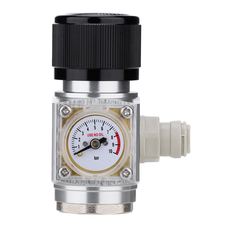 Beer CO2 Regulator Manufacturer, Beer Dispensing Regulator SupplierNingbo Noursun Industrial Co., Ltd is China beer CO2 regulator manufacturer and beer dispensing regulator OEM/ODM supplier, We specializi...View Product →
Soda and Sparkling Water Makers
Soda Water CO2 Regulator, CO2 Regulator For Soda Machine ManufacturerNoursun Industrial Co., Ltd is China soda water CO2 regulator manufacturer and co2 regulator for soda machine OEM/ODM supplier, We specia...View Product →
Hydroponics and Planted Aquariums
Custom Aquarium CO2 Regulator Manufacturer, OEM/ODM SupplierNingbo Noursun Industrial Co., Ltd is China aquarium CO2 regulator manufacturer and best co2 regulator for aquarium OEM/ODM supplier, We ...View Product →
Specialized and Low-Volume Applications
Materials, Testing, and What Quality Means in a Gas PRV
Installation and Maintenance Best Practices
Gas PRV FAQ
Can I use a CO2 regulator for nitrogen or argon?
What is the difference between a pressure regulating valve and a pressure relief valve?
Why does outlet pressure rise as the cylinder empties?
What does Cv mean and why does it matter?
How do I set the correct outlet pressure on a gas PRV?
How long does a gas pressure regulator last?
When You Need a Custom Gas PRV
Aug 17, 2026
A pressure regulator with relief valve combines two functions in one body: it reduces a high, variable inlet pressure to a stable lower outlet pressure, and it vents accumulated downstream pressure when that outlet pressure exceeds a preset limit. The relief function is not an optional add-on in many gas systems — it is the difference between a predictable process and an overpressure event that can damage equipment, loosen fittings, or produce inconsistent results. In practice, this means the regulator actively protects whatever sits downstream of it. A beverage carbonation loop, an aquarium CO2 injection line, a beer keg delivery line, or a paintball tank fill station all face the same risk: if the downstream valve is closed while the regulator keeps feeding pressure, the trapped gas can creep upward and exceed the working rating of hoses, solenoids, or pressure vessels. A regulator with a relief valve prevents that condition from becoming dangerous, simply by bleeding the excess through a calibrated vent. For OEMs and system builders, the practical advantage is equally clear. One combined component means fewer threaded joints, fewer leak points, and shorter assembly time. It also simplifies the bill of materials: instead of sourcing a separate pressure relief valve, a tee fitting, and the associated sealing hardware, you specify a single part number that handles both pressure reduction and pressure relief. The internal layout of a typical relieving regulator is straightforward. A diaphragm separates a control chamber fed by downstream pressure from a spring chamber where the setpoint is configured. When downstream pressure rises above the spring setting, the diaphragm lifts, and the excess gas escapes through a vent port in the center of the diaphragm assembly. In a non-relieving regulator, that center vent hole does not exist. If downstream pressure exceeds the setpoint, the regulator simply stops feeding gas, but it cannot release what is already trapped downstream. Pressure may therefore remain above the setpoint indefinitely, waiting for a downstream valve to open. In systems that dead-end regularly, that condition is both inconvenient and potentially hazardous. The design is intentionally self-resetting. A spring-loaded poppet or a direct diaphragm vent is always preferred for gas applications because it eliminates the need for manual reset. That makes the relieving regulator a truly automatic safety and precision device in one. The distinction between relieving and non-relieving designs has direct consequences for system safety, component cost, and daily usability. The table below summarizes the key differences in a format that makes the decision easier to communicate to suppliers or internal R&D teams. The bottom line is simple: if your downstream line can be isolated while the regulator remains pressurized, choose a relieving design. If the flow is continuous and the downstream volume is carefully managed, a non-relieving regulator may be acceptable, but it still leaves the system without built-in overpressure protection. Once you have settled on a regulator with a built-in relief function, the next decision is whether a single-stage or dual-stage configuration matches your application. Both can be supplied with an integrated relief valve, but they behave differently when inlet pressure changes. Single-stage regulators reduce the inlet pressure directly to the outlet setpoint. They are compact, low-cost, and sufficient when the inlet pressure is relatively steady. However, each time the source pressure drops—for example, as a CO2 cylinder empties—the outlet pressure tends to rise slightly. That drift is usually acceptable for simple carbonation systems, but not ideal for precision dosing. Dual-stage regulators act as two regulators in sequence. The first stage drops the cylinder pressure to an intermediate level, and the second stage delivers the final outlet pressure. Because the second stage always sees a constant intermediate inlet pressure, the outlet pressure stays essentially constant from a full cylinder to an nearly empty one. The trade-off is a bulkier body and a higher price, but the gain in stability is meaningful for aquariums, laboratory operations, and beverage dispensing where consistent carbonation matters. If you need to monitor pressure visually, choose a regulator with one or two gauges. A dual-gauge arrangement shows both the cylinder pressure and the downstream pressure, so you always know the supply status and the actual delivery value. That feature is especially valuable in aquariums, where CO2 content changes slowly and an unnoticed pressure drop can affect plant growth over several days. Not every application needs the same level of overpressure protection. But the four scenarios below share a common characteristic: they all dead-end at some point, which makes a relieving regulator the more robust choice. Carbonating water involves pressurizing a bottle or canister, shaking or injecting CO2, and then releasing or sealing the vessel. If the downstream valve is shut while the solenoid stays open, pressure can creep to dangerous levels. A relieving regulator vents the excess and keeps the carbonation level repeatable. For this reason, a dedicated carbonation regulator such as the RP07 soda water CO2 regulator is often the most reliable building block in a home soda machine or a countertop carbonation unit. Draft beer systems rely on CO2 to push beer from keg to tap at a pressure between 8 and 14 psi, depending on the beer style and the line length. A regulator that cannot relieve pressure will leave a freshly connected keg at excessive pressure if the system is turned on before the tap opens. The result can be over-carbonated beer or a ruptured keg line. The RP20 beer CO2 regulator addresses this directly by combining precise low-pressure regulation with a relief function for the headspace above the keg. That combination keeps pour quality consistent even after long shutdown periods. Aquarium and hydroponic systems often use a solenoid valve between the regulator and the diffuser to stop CO2 flow at night. When the solenoid closes, the pressure in the tubing between the regulator and the solenoid rises. A non-relieving regulator simply traps that pressure. A relieving regulator vents it through the diaphragm, so the next morning the system restarts at exactly the setpoint. The RP31 dual-gauge pressure regulator is especially useful here because its gauges let you confirm both cylinder content and downstream pressure at a glance. Paintball tanks are filled from a high-pressure source, and the output must be limited to the tank’s rated pressure. When the tank reaches the target pressure, the fill valve closes and the line dead-ends. A regulator with an integrated relief valve prevents overfilling by venting excess gas before it can over-pressurize the tank. That is a classic case where the relief function is not a convenience but a core safety feature. Choosing the correct pressure regulator with relief valve comes down to a handful of measurable parameters. Review these numbers against your system requirements, and ask your supplier for the actual test data rather than assuming that similar looking regulators behave the same way. When comparing products, pay special attention to the relief accuracy. A regulator with a nominal setpoint of 50 psi but a relief activation that only starts at 75 psi gives very different protection than one that vents as soon as pressure reaches 55 psi. Request the manufacturer’s performance curve so you can match the relief behavior to the pressure rating of your downstream components. Even a well-designed pressure regulator with relief valve is a precision component with moving parts and elastomer seals. Understanding the most common failure modes helps you maintain production uptime and avoid expensive surprises. The relief valve seat can gradually accumulate debris from the gas stream or suffer minor damage from repeated venting. A small amount of seat leakage allows gas to escape continuously, causing a minor hiss and slow pressure decay. The fix is regular inspection and, if necessary, replacing the seat or the full valve subassembly. The diaphragm flexes every time pressure changes. Over years of service it can harden, crack, or lose elasticity, especially in high-temperature environments. A failing diaphragm shows up as slow drifting outlet pressure or inconsistent relief activation. High-quality manufacturing facilities, like the ones described in Noursun’s engineering and production profile, typically use test fixtures that simulate tens of thousands of cycles to evaluate diaphragm longevity before a design enters mass production. Prolonged vibration or repeated adjustment cycles can cause the spring to settle slightly, shifting the outlet pressure by a few psi. This is why critical systems should be calibrated on a routine schedule. A dual-gauge design makes it easier to notice drift early because one glance at the gauges is enough to confirm that the setpoint has not changed. A pressure regulator is only as reliable as the manufacturing process behind it. Because the relief valve relies on tiny differences in spring tension, seat geometry, and diaphragm surface condition, small production inconsistencies can lead to large differences in performance between units. This is especially important for OEM buyers who install regulators into consumer products and need every unit to behave within the same tolerance window. When evaluating a supplier, look for evidence of in-house test capability rather than relying only on product photos. Noursun’s facilities, as described on their company background page, include professional laboratories that conduct endurance tests, environmental tests, mechanical strength tests, and safety-limit tests under simulated real-world conditions. A manufacturer that tests across these categories is statistically more likely to ship regulators with consistent relief activation and stable setpoints. Equally important is the variety of product configurations available. A manufacturer that offers multiple models across different applications can standardize your components and reduce the number of suppliers you need. The product range covers everything from mini regulators for soda systems to dual-stage regulators for aquarium use, so you can consolidate part numbers without compromising application fit. That kind of supplier alignment is especially valuable when you are moving from prototype to production volume. Beyond the regulator itself, there are a few practical workflow decisions that affect long-term satisfaction. First, determine whether you need a fixed or adjustable outlet pressure. Fixed-pressure regulators are less expensive and easier to seal against tampering, while adjustable models give you flexibility during testing and calibration. Second, decide on the connection size early. A 1/4-inch NPT or 1/8-inch NPT port may fit your prototype, but a larger port might be needed for higher flow. Downstream tubing diameter also matters because a long, narrow tube between the regulator and the equipment creates a pressure drop that changes dynamically with flow. Third, plan for spare parts. Regulator seats, springs, and replacement diaphragms are consumables. If your supplier does not offer spare parts for the relief mechanism, you may find yourself replacing an entire regulator for a minor repair. A manufacturer that carries spare parts is usually more confident in the repairability of its product design. Finally, confirm the minimum order quantity, lead time, and customization path. Many projects require a modified body, a different gauge range, or a custom spring to achieve a specific outlet pressure range. The ability to request application-specific adjustments from a single manufacturer, rather than trying to modify a standard product yourself, shortens the product development cycle. Noursun’s application-focused engineering approach is designed around exactly this kind of collaborative customization. A pressure regulator controls the downstream pressure by throttling the flow of gas from the source. A pressure relief valve only opens when the downstream pressure exceeds a preset level, releasing the excess and then closing again. A combined regulator with relief valve performs both actions inside one housing. They work on the same principle, but a relief valve is typically used in liquid or low-pressure gas systems to control pressure, while a safety valve is designed to rapidly release a large volume of gas or liquid and is usually associated with preventing catastrophic failure. In the context of a pressure regulator, the relief valve functions as a precision overpressure control device, not as an emergency dump valve. No. Non-relieving regulators do not have a vent path. They are sometimes used in continuous-flow applications or as back-pressure regulators where pressure relief is handled by a separate, external valve. Always check the product specification sheet to confirm whether a regulator is relieving or non-relieving before integrating it. No. A relief valve can only vent excess pressure when it is already too high; it cannot provide steady downstream pressure control. If relief is the only problem in your system, you could add a separate relief valve, but a combined regulator with relief valve is a more elegant and safer design because the two functions are calibrated together. Close a downstream valve, isolate the downstream volume, and observe the outlet pressure gauge. If the pressure rises noticeably above the setpoint and then settles back to the setpoint, the relief function is operating. If the pressure stays elevated, the relief valve may be blocked or faulty. In a dual-gauge regulator, this check is easy to perform without additional test equipment. Early opening is usually caused by debris trapped on the relief seat, a broken spring, or an incorrectly assembled relief subassembly. In some cases, a pressure spike that is too fast for the diaphragm to regulate can also cause transient venting. If the problem persists, replace the spring or service the relief seat. For any system that can dead-end or that requires predictable downstream pressure, a pressure regulator with relief valve is the safer and more reliable engineering choice. It gives you pressure reduction, overpressure protection, and automatic reset capability in a single component. That means fewer fittings, faster assembly, and one less failure point in your design. When sourcing, pay attention to the relief flow capacity, the relief activation point, the outlet pressure stability, and the manufacturer’s ability to test and customize. For OEM projects, working directly with an engineering-oriented manufacturer can eliminate the back-and-forth of trying to adapt off-the-shelf products. If you are ready to evaluate your project requirements against an existing range, contact Noursun directly and provide your target pressure range, gas type, and installation constraints to receive product recommendations that match your actual operating conditions.What Is a Pressure Regulator with Relief Valve?
How the Relief Valve Works Inside a Regulator
What Happens When Downstream Pressure Spikes
Relieving vs. Non-Relieving Regulators: A Side-by-Side Comparison
Feature
Relieving Regulator
Non-Relieving Regulator
Overpressure response
Automatically vents excess pressure
Cannot release trapped pressure
Dead-end service
Safe and self-correcting
Pressure can remain above setpoint
External vent line
Required for toxic or flammable gas
Not applicable
Seat wear
Generally lower, because latching pressure is avoided
Can be higher in frequent dead-end cycling
Best fit
Beverage, aquarium, medical gas, dead-end pneumatic
Inert gas supply, continuous flow, secondary isolation
Single-Stage vs. Dual-Stage: Which Configuration Should You Choose?
Application Areas That Actually Need a Relief Valve
Soda and Sparkling Water Systems
Soda Water CO2 Regulator, CO2 Regulator For Soda Machine ManufacturerNoursun Industrial Co., Ltd is China soda water CO2 regulator manufacturer and co2 regulator for soda machine OEM/ODM supplier, We specia...View Product →
Beer and Keg Dispensing
Beer CO2 Regulator Manufacturer, Beer Dispensing Regulator SupplierNingbo Noursun Industrial Co., Ltd is China beer CO2 regulator manufacturer and beer dispensing regulator OEM/ODM supplier, We specializi...View Product →
Aquarium and Hydroponics CO2 Injection
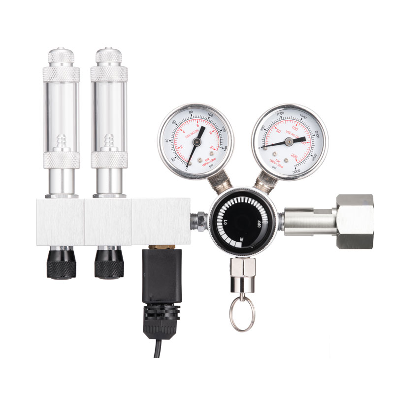 Custom Dual Gauge Pressure Regulator Manufacturer, OEM/ODM SupplierNingbo Noursun Industrial Co., Ltd is China dual gauge pressure regulator manufacturer and dual gauge gas regulator OEM/ODM supplier, We ...View Product →
Paintball Tank Filling
Key Specifications to Evaluate Before Purchasing
Common Failure Modes and How to Prevent Them
Relief Valve Seat Leakage
Diaphragm Fatigue
Spring Setpoint Shift
Why the Manufacturer’s Process Matters
Practical Buying Considerations for OEM and Maintenance Teams
Frequently Asked Questions
What is the difference between a pressure regulator and a pressure relief valve?
Is a relief valve the same as a safety valve?
Do all pressure regulators have an internal relief valve?
Can a pressure relief valve replace a pressure regulator?
How do I know if the relief valve on my regulator is working?
What causes a relief valve to open too early?
Final Recommendation
Aug 10, 2026
Open a CO2 cylinder valve and you are dealing with roughly 850 psi inside the cylinder at room temperature. Connect that pressure directly to a soda carbonator, an aquarium CO2 diffuser, or a beer keg line, and the system will over-carbonate, waste gas, or simply refuse to operate safely. A gas regulator exists to prevent that outcome. It does two jobs at once: it steps cylinder pressure down to a usable level, and it holds that level steady while the cylinder pressure drops and downstream demand fluctuates. Every gas regulator that Noursun builds for beverage dispensing, beer, and aquarium systems works on the same mechanical principle: a spring and a flexible diaphragm continuously balance the outlet pressure against a preset reference force. Once you understand that balance, terms like droop, lock-up, and inlet-pressure effect stop being marketing language and become design decisions you can evaluate before you buy. A gas regulator is a self-operating pressure-control valve that takes a high, variable inlet pressure, reduces it to a lower outlet pressure, and keeps that outlet pressure inside a usable band as flow conditions change. Unlike a needle valve that a person adjusts by hand, a regulator senses its own output pressure and corrects the valve opening automatically, with no electricity and no external controller. Three functional elements appear in every mechanical regulator: a spring that sets the target pressure, a diaphragm or piston that senses the actual outlet pressure, and a poppet-and-seat assembly that restricts gas flow. The spring pushes the valve open; the gas pressure under the diaphragm pushes it closed. The regulator continuously seeks the equilibrium at which the valve opening passes enough gas to hold the set outlet pressure. The difference between pressure reduction and pressure regulation matters. A pressure reducer is a fixed restriction that lowers pressure once. A pressure regulator is a feedback mechanism that adjusts the restriction in response to changing demand. If you install a reducer where the application needs a regulator, the outlet pressure drifts as the cylinder empties, so downstream equipment behaves inconsistently. The internal geometry decides how well the regulator holds its set pressure. A correctly sized seat, a responsive diaphragm, and a spring with a predictable rate define the accuracy curve. At Noursun's manufacturing facility, each component is tuned to the intended gas and application range, which is why a soda water regulator and an aquarium CO2 regulator share the same working principle but not the same calibration. The operation of a typical single-stage regulator happens in a continuous cycle. Here is the sequence in its simplest form: This cycle is not slow. The diaphragm and poppet respond within milliseconds to pressure changes. Even a large downstream flow change produces only a brief dip in pressure before the regulator recovers, provided the unit is correctly sized. Piston-type regulators replace the diaphragm with a sliding piston. Piston designs tolerate higher inlet pressures and wider temperature swings, but they tend to be more sensitive to solid contamination. Diaphragm designs give finer accuracy at low pressure and are the common choice for beverage and aquarium CO2 service. A single-stage regulator reduces cylinder pressure to working pressure in one step. Because the poppet area is exposed to the inlet pressure, any change in inlet pressure shifts the outlet set point slightly. This is the inlet-pressure effect. A full CO2 cylinder at 850 psi delivers a slightly higher outlet pressure than a nearly empty cylinder at 200 psi, even if the adjustment knob stays untouched. A dual-stage regulator separates the job into two steps. The first stage reduces the cylinder pressure to a fixed intermediate pressure, usually a few hundred psi. The second stage then regulates that already-stable intermediate pressure down to the final working pressure. Because the second stage always sees the same inlet pressure, the outlet pressure stays nearly constant from the first use of the cylinder to the last. Dual-stage regulators justify their higher cost whenever the process cannot tolerate a pressure shift. Aquarium CO2 reactors are the clearest example: a drift of 1 to 2 psi changes the dosing rate noticeably. For beverage dispensing, where the set pressure can tolerate 2 to 3 psi of drift, a well-made single-stage regulator handles the job at a lower cost. When you compare regulator datasheets, six terms explain most of the difference between a reliable part and a frustrating one. Buyers who understand them can catch a mismatch before it becomes a field failure. In Noursun's test records, the gap between an acceptable regulator and an excellent one usually shows up in creep and hysteresis, not in the headline maximum inlet pressure. Leak testing at shutoff and repeated cycle testing catch defects that a standard pressure check misses. The same operating principle appears across many industries, but each application asks different questions: what gas, what pressure range, what flow rate, and what stability requirement. Soda water and sparkling water systems: A CO2 regulator typically reduces cylinder pressure at 800 to 2000 psi down to 40 to 60 psi for the carbonator. The RP07 soda water CO2 regulator covers this range with a single-stage design and dual pressure gauges, so operators can see both cylinder and line pressure at a glance. Beer dispensing: Keg pressure is usually set between 10 and 30 psi, depending on beer temperature and carbonation level. The RP20 beer CO2 regulator delivers stable low-pressure output and is sized for the flow a typical kegerator demands. Aquarium and hydroponics: Low flow and high stability matter far more than large capacity. The RP23 dual-stage aquarium CO2 regulator keeps dosing consistent as the cylinder empties, which is exactly the condition that defeats a single-stage design. The full range of gas applications also includes paintball tanks, gas manifolds, and custom industrial equipment. In every case, the matching criteria stay the same: verify the gas purity, the maximum source pressure, the outlet pressure window, and the maximum flow the equipment can draw. Even a correctly selected regulator will drift, creep, or fail early if installation and maintenance are careless. These practices cover most CO2 and inert-gas regulator installations: For CO2 service, keep the flow demand below the regulator's maximum rated capacity. Excessive flow cools the seat area rapidly, which can create condensation or seat damage, and it exaggerates droop. Before contacting a supplier, write down the operating parameters. A complete specification prevents misquotes and mismatched parts. The critical inputs are: A manufacturer with production experience, rather than a distributor reselling a generic part, asks these questions before quoting. That is one advantage of working directly with a factory: the part you receive has been designed for the gas and the operating band you actually run. It throttles the flow through a small seat opening. The gas moves from a high-pressure region, through a restricted opening, into a larger low-pressure chamber. The restriction converts the energy of the high-pressure gas into velocity and heat, so the pressure in the low-pressure chamber is lower. The diaphragm then adjusts the size of that opening automatically to keep the downstream pressure at the set value. That rise is lock-up pressure. When flow stops, the poppet must reseat completely. The sensing element can only react to the pressure it feels, so a small overshoot of a few percent is normal before the valve seals. A large continuous rise, however, indicates creep caused by a dirty or damaged seat. A gas regulator controls pressure, not flow. A flow meter measures how much gas passes per minute, and a flow controller adjusts a needle valve to hold a set rate. In many aquarium and lab systems, the two are combined: the regulator stabilizes the supply pressure, and a needle valve controls the bubble count or mass flow. Not without checking two conditions: the inlet connection must match the cylinder valve, and the outlet pressure range plus seal materials must suit the gas. A soda water CO2 regulator with an outlet range of 0 to 60 psi is not appropriate for argon at higher pressure. Dedicated dual-stage argon regulators are specified for that service. Because the first stage absorbs the change in cylinder pressure. From a full cylinder at 850 psi down to a nearly empty one at 100 psi, the intermediate pressure stays at the first stage's set value. The second stage therefore sees a constant inlet pressure, and its outlet stays virtually fixed. A single-stage regulator has no intermediate buffer, so the inlet-pressure effect appears directly at the outlet. For home and light commercial equipment, inspect the regulator once a year for output drift, creep, and seat wear. For continuous industrial use, rebuild or replace the regulator when the outlet pressure no longer stays inside your acceptable tolerance. The diaphragm and seat are wear items; in most designs they can be replaced without changing the whole body. Understanding how a gas regulator works turns a part number into a decision. If you know the outlet pressure must stay steady at 30 psi while the cylinder pressure falls from 850 psi to 200 psi, you already know whether a single-stage or a dual-stage regulator is the right answer. Noursun has manufactured pressure-control components since 2012 and ships regulators for beverage, aquarium, and dispensing applications to customers in Europe, North America, and Asia. If you need a regulator matched to your system, or a custom pressure-control solution for a new product, contact our engineering team with your operating parameters.What Is a Gas Regulator and Why Does the Design Matter?
How Does a Gas Regulator Work? Step-by-Step Mechanics
Element
Role in the regulator
Common failure symptom
Spring and adjusting knob
Sets the reference outlet pressure
Output pressure drifts or no longer reaches the set point
Diaphragm or piston
Senses outlet pressure and moves the valve
Erratic outlet pressure or gas escaping from the vent
Poppet and seat
Throttles the flow of gas
Creep: outlet pressure keeps climbing after shutoff
Single-Stage vs Dual-Stage Regulators: What Changes Inside
Criterion
Single-stage
Dual-stage
Outlet pressure stability
Moderate; drifts as the cylinder empties
High; stable across the cylinder life
Parts and internal complexity
Lower; compact body
Higher; slightly longer body
Cost
Lower
Higher
Typical use
Soda machines, beer dispensing, paintball
Aquarium CO2, laboratories, precision processes
Key Performance Terms That Define Regulator Quality
Common Applications and How to Match the Regulator
Soda Water CO2 Regulator, CO2 Regulator For Soda Machine ManufacturerNoursun Industrial Co., Ltd is China soda water CO2 regulator manufacturer and co2 regulator for soda machine OEM/ODM supplier, We specia...View Product →
Beer CO2 Regulator Manufacturer, Beer Dispensing Regulator SupplierNingbo Noursun Industrial Co., Ltd is China beer CO2 regulator manufacturer and beer dispensing regulator OEM/ODM supplier, We specializi...View Product →
Custom Aquarium CO2 Regulator Manufacturer, OEM/ODM SupplierNingbo Noursun Industrial Co., Ltd is China aquarium CO2 regulator manufacturer and best co2 regulator for aquarium OEM/ODM supplier, We ...View Product →
Installation and Maintenance Best Practices
How to Choose a Gas Regulator for Your Project
Gas Regulator FAQ
How exactly does a gas regulator lower pressure?
Why does outlet pressure rise slightly when I close the downstream valve?
What is the difference between a gas regulator and a flow controller?
Can a CO2 regulator be used for argon or nitrogen?
Why does a dual-stage regulator hold pressure better as the cylinder empties?
How often should a gas regulator be serviced or replaced?
ADD: No. 50, Zhongxing East Road, Xikou Town, Fenghua District, Ningbo City, Zhejiang Province, P.R. China
0086-574-88881358
0086-574-88473625
About Us
Industry Applications
News & Events
